 |
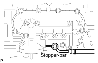
Connect the vacuum pump oil inlet hose with 2 new gaskets and the union bolt.
- Torque:
- 14 N*m{ 140 kgf*cm , 10 ft.*lbf }
- CAUTION:
- Catch a stopper-bar of the inlet hose with the oil filter bracket.
ENGINE OIL COOLER > INSTALLATION |
| 1. INSTALL OIL COOLER ASSEMBLY |
Install the 2 new gaskets, and the oil cooler with the 4 nuts to the filter bracket.
| 2. INSTALL OIL FILTER BRACKET SUB-ASSEMBLY |
Install a new gasket and oil filter bracket with the 10 bolts and 2 nuts.
| 3. INSTALL VACUUM PUMP OIL INLET HOSE |
|
Connect the vacuum pump oil inlet hose with 2 new gaskets and the union bolt.
| 4. INSTALL OIL FILTER SUB-ASSEMBLY |
Check and clean the oil filter installation surface.
Apply clean engine oil to the rubber gasket of a new oil filter.
Instal the oil filter, and tighten it by hand until the rubber gasket contacts the installation surface.
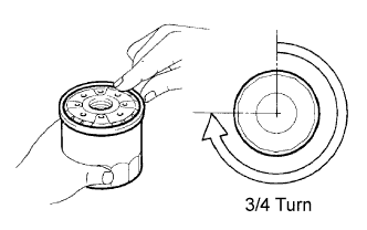 |
Using SST, tighten it by an additional 3/4 turn to seat the filter.
| 5. INSTALL EXHAUST MANIFOLD |
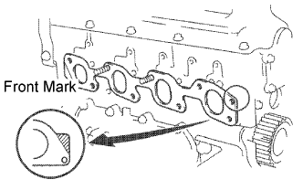 |
Install a new gasket to the cylinder head.
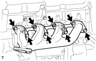 |
Install the exhaust manifold with the 6 bolts and 2 new nuts. Uniformly tighten the bolts and nuts in several steps.
| 6. INSTALL EXHAUST MANIFOLD HEAT INSULATOR NO.1 |
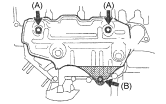 |
Install the heat insulator with the 3 bolts.
| 7. INSTALL EXHAUST PIPE ASSEMBLY FRONT |
| 8. INSTALL GENERATOR W/ VACUUM PUMP ASSEMBLY |
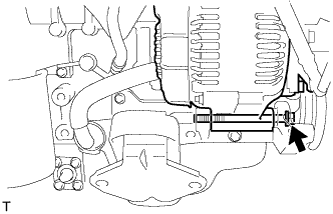 |
Temporarily tighten the bolt and generator w/ vacuum pump assembly.
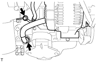 |
Install the clip with the hose connected.
Install the bolt with the hose connected.
| 9. INSTALL COMPRESSOR MOUNTING BRACKET (w/ Air Conditioning) |
Temporarily install the compressor mounting bracket with the 4 bolts.
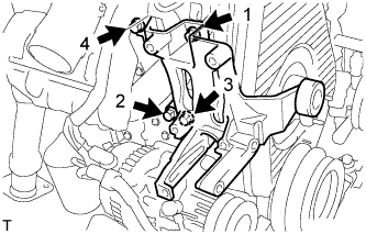 |
Using several steps, uniformly install and tighten the 4 bolts in the sequence shown in the illustration.
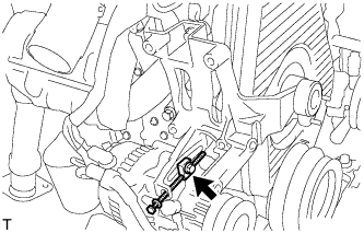 |
Temporarily tighten the bolt and spacer.
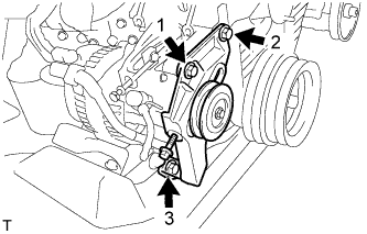 |
Temporarily install the compressor mounting bracket with the 3 bolts.
Using several steps, uniformly install and tighten the 3 bolts in the sequence shown in the illustration.
| 10. INSTALL COMPRESSOR AND MAGNETIC CLUTCH (w/ Air Conditioning) |
| 11. INSTALL FAN AND GENERATOR V BELT (w/ Air Conditioning) |
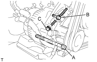 |
Install the V belt.
Tightening the bolt C, adjust the tension of the V belt.
Tighten the bolts A and B.
Check the tension of the V belt. (Click here)
| 12. INSTALL FAN AND GENERATOR V BELT (w/o Air Conditioning) |
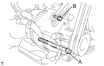 |
Install the V belt.
Using a bar, adjust the tension of the V belt.
Tighten the bolts A and B.
Check the tension of the V belt. (Click here)
| 13. INSTALL V (COOLER COMPRESSOR TO CRANKSHAFT PULLEY) BELT NO.1 (w/ Air Conditioning) |
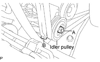 |
Install the V belt.
Tightening the bolt B, adjust the tension of the V belt.
Tighten nut A.
Check the tension of the V belt. (Click here)
| 14. INSTALL VANE PUMP V BELT |
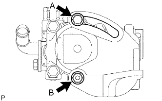 |
Install the V belt.
Using a bar, adjust the tension of the V-ribbed belt.
Tighten the bolt A and nut B.
Check the tension of the V belt. (Click here)
| 15. INSTALL OIL LEVEL GAGE GUIDE |
Install the level gage guide with the 2 bolts.
| 16. INSTALL OIL LEVEL GAGE SUB-ASSEMBLY |
| 17. INSTALL INTAKE AIR CONNECTOR BRACKET |
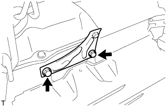 |
Install the 2 bolts and intake air connector bracket.
| 18. INSTALL INTAKE AIR CONNECTOR SUB-ASSEMBLY |
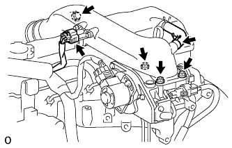 |
Install a new gasket and intake air connector with the bolt and 3 nuts.
Connect the turbo pressure sensor connector.
Connect the ventilation hose.
| 19. ADD ENGINE OIL |
| 20. ADD ENGINE COOLANT |
Close the engine drain plug.
Close the radiator drain cock plug.
Slowly fill the cooling system with coolant.
Slowly pour coolant into the radiator reserve tank until it reaches the FULL line.
Install the radiator cap to the radiator reserve tank.
Press the inlet and outlet radiator hoses several times by hand while warming up the engine.
Stop the engine, and wait until the engine coolant cools down.
Add coolant to the FULL line of the radiator reservoir.
| 21. CHECK FOR ENGINE OIL LEAKS |
| 22. CHECK FOR ENGINE COOLANT LEAKS |
Fill the radiator with coolant and attach a radiator cap tester to the radiator.
Warm up the engine.
Using a radiator cap tester, increase the pressure inside the radiator to 118 kPa (1.2 kgf/cm2, 17.1 psi), and check that the pressure does not drop.
| 23. INSTALL ENGINE SERVICE HOLE SUB COVER SUB-ASSEMBLY |
Install the 5 bolts and engine service hole cover.
| 24. INSTALL FRONT DOOR SCUFF PLATE RH |
| 25. INSTALL FRONT SEAT ASSEMBLY RH |
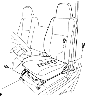 |
Connect the front seat inner belt assembly connector and install the front seat assembly.
Align the front seat assembly adjuster pin with the holes in the body.
Move the front seat assembly to the rearmost position.
Temporarily tighten the 2 bolts on the front side of the front seat assembly.
Move the front seat assembly fully forward.
Temporarily tighten the 2 bolts on the rear side of the front seat assembly.
Move the front seat assembly to the rearmost position.
Fully tighten the 2 bolts on the front side of the front seat assembly in the order of outer and inner side.
Move the front seat assembly fully forward.
Fully tighten the 2 bolts on the rear side of the front seat assembly in the order of outer and inner side.