REMOVAL
Removal / installation · Vehicles built from Oct 2014
| 1. REMOVE PROPELLER SHAFT ASSEMBLY |

Put matchmarks on both flanges.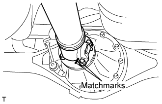

Remove the 4 nuts, bolts and washers.
- HINT:
- If the flange connection is hard to separate, temporarily tighten one nut only and evenly tap the flange with a brass bar and hammer to separate the propeller shaft assembly from the differential companion flange.
Remove the propeller shaft assembly.
Insert SST in the transmission to prevent oil leakage.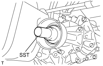
- NOTICE:
- Do not damage the oil seal.
Use the following SST for the automatic transmission
- SST
- 09325-40010
Use the following SST for the manual transmission
- SST
- 09325-20010
| 2. INSPECT PROPELLER SHAFT ASSEMBLY |
Visually check the propeller shaft assembly.
Using a dial indicator, inspect the runout of the shaft tube.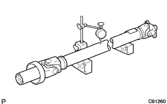
- Runout of propeller shaft:
Shaft tube length mm (in.)
Maximum runout mm (in.)
800 (31.496) or more
0.4 (0.0157)
Less than 800 (31.496)
0.3 (0.0118)
| 3. INSPECT UNIVERSAL JOINT SPIDER ASSEMBLY |
Check that the spider bearing rotates smoothly.
Check that there is no play in the spider bearing.
Using a spring tension gauge, hang the hook of the spring tension gauge on the bolt hole of the flange yoke and measure the rotating force.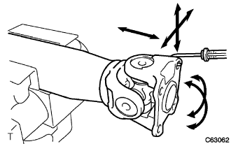
- Maximum:
- 1.1 N*m (11.2 kgf*cm, 9.68 in.*lbf)
- NOTICE:
- Measurement of rotating force should be done at 2 positions for each universal joint by 90° in opposite directions (flange yoke side and end yoke side). When the rotating force is less than the standard, use a thicker retainer ring. When it exceeds the standard, use a thinner one.