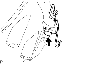
REMOVAL
Removal / installation · Vehicles built from Jan 2017
Versions by build date: Oct 2014 – Dec 2016 from Jan 2017
| 1. DISCONNECT CABLE FROM NEGATIVE BATTERY TERMINAL |
| 2. DRAIN MANUAL TRANSMISSION OIL |

Remove the filler plug and gasket.
Remove the drain plug and gasket, and drain the oil.
Install the drain plug with a new gasket.
- Torque:
- 37 N*m{ 377 kgf*cm , 27 ft.*lbf }
| 3. REMOVE EXHAUST PIPE ASSEMBLY FRONT (for Long Wheelbase) |
w/ Secondary air injection system:
Disconnect the fuel ratio sensor connector.
Remove the fuel ratio sensor. (Click here)
For unleaded gasoline engine:
Disconnect the oxygen sensor connector.
Remove the oxygen sensor. (Click here)
Remove the 4 bolts, 2 nuts, and 2 compression springs.
Remove the 2 gaskets from the exhaust pipe assembly front.
Disconnect the exhaust pipe support, and remove the exhaust pipe assembly front.
| 4. REMOVE EXHAUST PIPE ASSEMBLY FRONT (for Super Long Wheelbase) |
w/ Secondary air injection system:
Disconnect the fuel ratio sensor connector.
Remove the fuel ratio sensor. (Click here)
For unleaded gasoline engine:
Disconnect the oxygen sensor connector.
Remove the oxygen sensor. (Click here)
Remove the 4 bolts, 2 nuts, and 2 compression springs.
Remove the 2 gaskets from the exhaust pipe assembly front.
Disconnect the exhaust pipe support, and remove the exhaust pipe assembly front.
| 5. REMOVE PROPELLER SHAFT ASSEMBLY (for Long Wheelbase) |
Put matchmarks on both flanges.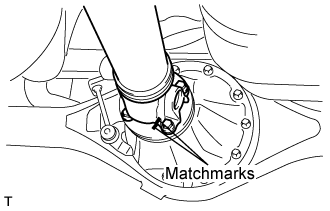

Remove the 4 nuts, bolts and washers.
- HINT:
- If the flange connection is hard to separate, temporarily tighten one nut only and evenly tap the flange with a brass bar and hammer to separate the propeller shaft assembly from the differential companion flange.
Remove the propeller shaft assembly.
Insert SST in the transmission to prevent oil leakage.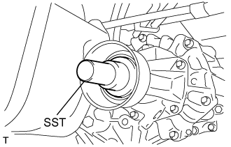
- NOTICE:
- Do not damage the oil seal.
Use the following SST for the automatic transmission
- SST
- 09325-40010
Use the following SST for the manual transmission
- SST
- 09325-20010
| 6. REMOVE PROPELLER WITH CENTER BEARING SHAFT ASSEMBLY (for Super Long Wheelbase) |
Put matchmarks on both flanges.
Remove the 4 nuts, bolts and washers.
- HINT:
- If the flange connection is hard to separate, temporarily tighten one nut only and evenly tap the flange with a brass bar and hammer to separate the propeller with center bearing shaft assembly from the differential companion flange.
Remove the 2 bolts and center support bearing assembly No.1.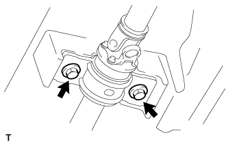
Remove the propeller with center bearing shaft assembly.
Insert SST in the transmission to prevent oil leakage.
- NOTICE:
- Do not damage the oil seal.
Use the following SST for the automatic transmission.
- SST
- 09325-40010
Use the following SST for the manual transmission.
- SST
- 09325-20010
| 7. SEPARATE TRANSMISSION CONTROL CABLE ASSEMBLY |
Put matchmarks on the control cable assembly and the outer lever.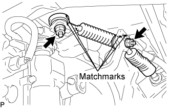
Remove the 2 nuts and separate the transmission control cable from the outer lever.
Using a screwdriver, disengage the claws of the 2 clips.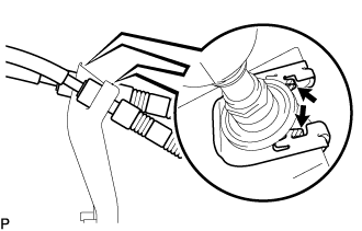
Remove the transmission control cable and 2 clips from the transmission control cable bracket No.1.
| 8. DISCONNECT WIRE HARNESS |
Disconnect the 2 connectors and clamps.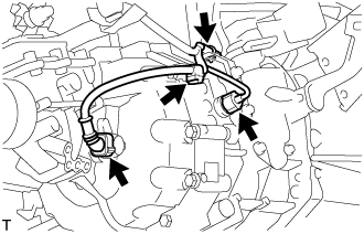
| 9. SEPARATE CLUTCH RELEASE CYLINDER ASSEMBLY |
Remove the 2 bolts and separate the clutch release cylinder.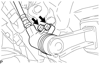
| 10. REMOVE STARTER ASSEMBLY (for 1.6 kW Type) |
Remove the 2 bolts, then remove the ground cable and bracket.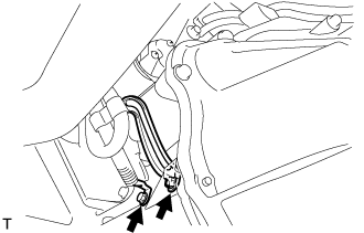
Remove the nut and disconnect the wire harness from terminal 30.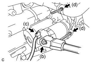
Disconnect the terminal 50 connector from the starter assembly.
Remove the 2 bolts and the starter assembly.
| 11. REMOVE STARTER ASSEMBLY (for 1.7 kW Type) |
Remove the 2 bolts, then disconnect the ground cable and wiring harness clamp bracket.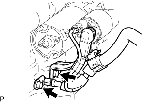
Open the terminal cap.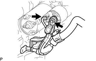
Disconnect the starter connector.
Remove the nut and disconnect the starter wire.
Remove the 2 bolts and starter assembly.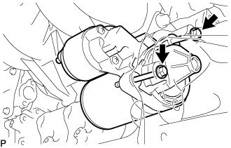
| 12. REMOVE MANUAL TRANSMISSION UNIT ASSEMBLY |
Support the manual transmission unit with a transmission jack.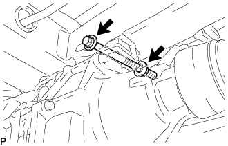
Remove the bolt, nut, and 2 washers, and separate the transmission unit from the frame.
Remove the 8 bolts and manual transmission unit.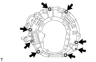
| 13. REMOVE REAR ENGINE MOUNTING INSULATOR ASSEMBLY |
Remove the 4 bolts and rear engine mounting insulator assembly.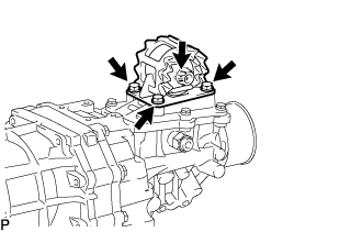
| 14. REMOVE TRANSMISSION CONTROL CABLE BRACKET NO.1 |
Remove the 2 bolts and transmission control cable bracket No.1.
| 15. REMOVE WIRE HARNESS CLAMP BRACKET |
Remove the bolt and wire harness clamp bracket.