REMOVAL
Removal / installation · Vehicles built from Jan 2017
Versions by build date: Jan 2015 – Dec 2016 from Jan 2017
| 1.
REMOVE TIMING CHAIN OR BELT COVER SUB-ASSEMBLY |
 |
(Click here)
| 2.
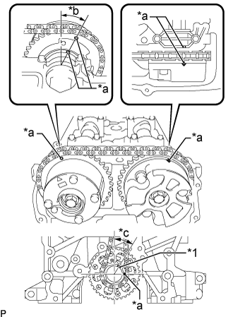
SET NO. 1 CYLINDER TO TDC/COMPRESSION
|
|
Temporarily install the crankshaft pulley bolt.
- Rotate the crankshaft clockwise so that the timing marks on the crankshaft timing gear and camshaft timing gears are as shown in the illustration.
Text in Illustration
*1
|
Key
|
*a
|
Timing Mark
|
*b
|
Approximately 13°
|
*c
|
Approximately 30°
|
- HINT:
- If the timing marks do not align, rotate the crankshaft clockwise again and align the timing marks.
Remove the crankshaft pulley bolt.
| 3.
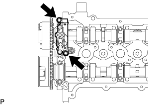
REMOVE CYLINDER HEAD COVER CONNECTOR SUB-ASSEMBLY
|
|
- Remove the 2 bolts and cylinder head cover connector sub-assembly.
Remove the No. 2 camshaft bearing cap oil hole gasket and 3 No. 3 camshaft bearing cap oil hole gaskets from the camshaft bearing cap.
| 4.
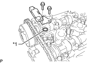
REMOVE TIMING CHAIN GUIDE
|
|
- Remove the 2 bolts, timing chain guide and O-ring.
Text in Illustration
*1
|
O-Ring
|
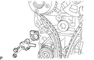
| 5.
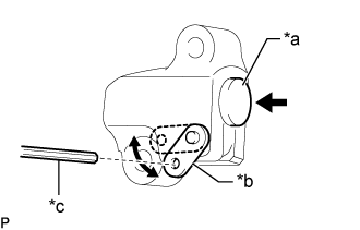
REMOVE NO. 1 CHAIN TENSIONER ASSEMBLY
|
|
- NOTICE:
- When the No. 1 chain tensioner assembly is removed, do not rotate the crankshaft.
- When the chain is removed and the camshaft needs to be rotated, rotate the crankshaft 90° to the right.
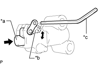
- Move the stopper plate upward to release the lock and push the plunger deep into the tensioner.
Text in Illustration
*a
|
Plunger
|
*b
|
Stopper Plate
|
*c
|
Hexagon Wrench
|
Move the stopper plate downward to set the lock, and insert a hexagon wrench into the stopper plate hole.
- Remove the bolt, nut, No. 1 chain tensioner assembly and gasket.
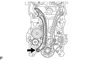
| 6.
REMOVE CHAIN TENSIONER SLIPPER
|
|
- Remove the bolt and chain tensioner slipper.
| 7.
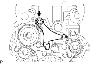
REMOVE NO. 1 CHAIN VIBRATION DAMPER
|
|
- Remove the bolt, nut, and No. 1 chain vibration damper.
| 8.
REMOVE CHAIN SUB-ASSEMBLY |
|
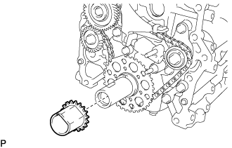
| 9.
REMOVE CRANKSHAFT TIMING GEAR OR SPROCKET
|
|
- Remove the crankshaft timing gear or sprocket from the crankshaft.
| 10.
REMOVE NO. 2 CHAIN VIBRATION DAMPER
|
|
- Move the stopper plate downward to release the lock, and push the plunger deep into the tensioner.
Text in Illustration
*a
|
Plunger
|
*b
|
Stopper Plate
|
*c
|
Hexagon Wrench
|
Move the stopper plate upward to set the lock, and insert a hexagon wrench into the stopper plate hole.
- Remove the bolt and No. 2 chain vibration damper.
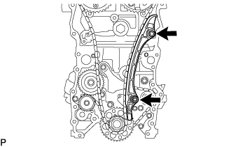
| 11.
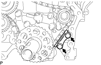
REMOVE NO. 3 CHAIN VIBRATION DAMPER
|
|
- Remove the 2 bolts and No. 3 chain vibration damper.
| 12.
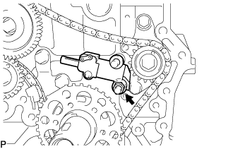
REMOVE NO. 2 CHAIN TENSIONER ASSEMBLY
|
|
- Remove the hexagon wrench from the No. 2 chain tensioner assembly.
Remove the nut and No. 2 chain tensioner assembly.
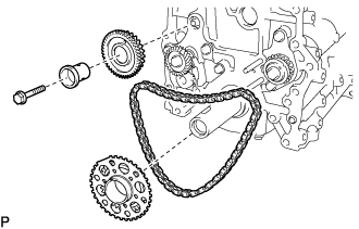
| 13.
REMOVE NO. 2 CHAIN SUB-ASSEMBLY
|
|
- Remove the bolt, balanceshaft drive gear shaft and balanceshaft drive gear.
Remove the No. 2 crankshaft timing sprocket and No. 2 chain sub-assembly.