Home › BODY › ENGINE HOOD / DOOR › BACK DOORREASSEMBLY
Removal / installation · Vehicles built Oct 2014 – Nov 2015
Versions by build date: Oct 2014 – Nov 2015 Dec 2015 – Dec 2016 from Jan 2017
1.
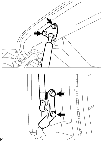
INSTALL BACK DOOR STAY ASSEMBLY LH
Clean the threads of the bolt with non-residue solvent (when reusing the bolt).
Apply adhesive to the threads of the bolt (when reusing the bolt).
Adhesive:
Toyota Genuine Adhesive 1324, Three Bond 1324 or equivalent.
Install the back door stay assembly LH with the 4 bolts.
Torque:
22 N*m{
224 kgf*cm
, 16 ft.*lbf
}
2.
INSTALL BACK DOOR STAY ASSEMBLY RH
HINT:
Use the same procedure for the LH side.
3.
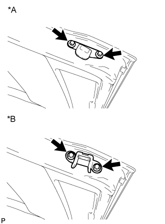
INSTALL BACK DOOR STOPPER LH
Install the back door stopper LH with the 2 bolts.
Text in Illustration
*A
for Standard Area Spec
*B
for Rough Road Area Spec
Torque:
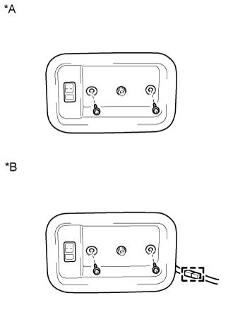
7.5 N*m{
76 kgf*cm
, 66 in.*lbf
}
4.
INSTALL BACK DOOR STOPPER RH
HINT:
Use the same procedure for the LH side.
5.
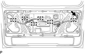
INSTALL NO. 2 BACK DOOR WIRE
Attach the 6 clamps to install the No. 2 back door wire. Install the bolt.
6.
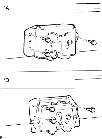
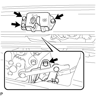
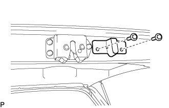
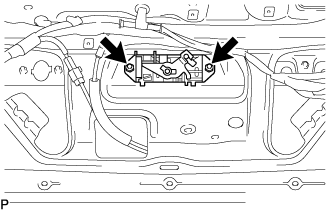
INSTALL BACK DOOR LOCK ASSEMBLY (w/o Easy Closer)
Apply MP grease to the sliding parts of the back door lock assembly.
Install the back door lock assembly with the 3 bolts.
Text in Illustration
*A
w/o Rear Bumper Step
*B
w/ Rear Bumper Step
Torque:
8.0 N*m{
82 kgf*cm
, 71 in.*lbf
}
7.
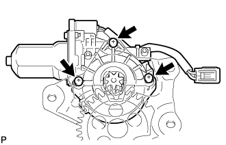
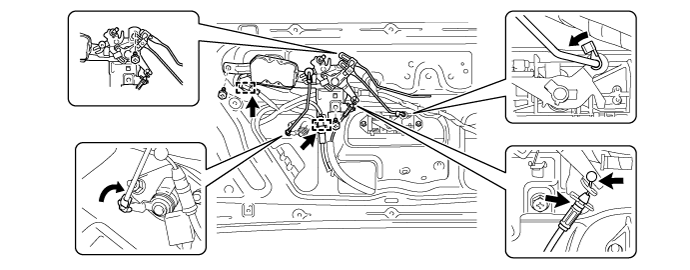
INSTALL DOOR CONTROL MOTOR (w/ Easy Closer)
Apply MP grease to the sliding parts of the door control motor.
Using a T25 "TORX" socket wrench, install the door control motor with the 3 "TORX" screws.
Torque:
5.4 N*m{
55 kgf*cm
, 48 in.*lbf
}
HINT:
A new door control motor uses self-tapping screws to thread new installation holes when the self-tapping screws are inserted.
8.
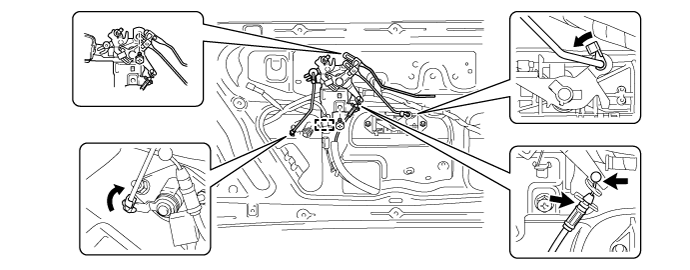
INSTALL BACK DOOR CLOSER MOTOR ASSEMBLY (w/ Easy Closer)
Apply MP grease to the sliding parts of the back door lock assembly.
Install the back door lock assembly with the 4 bolts.
Torque:
8.0 N*m{
82 kgf*cm
, 71 in.*lbf
}
9.
INSTALL BACK DOOR LOCK ASSEMBLY (w/ Easy Closer)
Apply MP grease to the sliding parts of the back door lock assembly.
Install the back door lock assembly with the 4 bolts.
Torque:
8.0 N*m{
82 kgf*cm
, 71 in.*lbf
}
10.
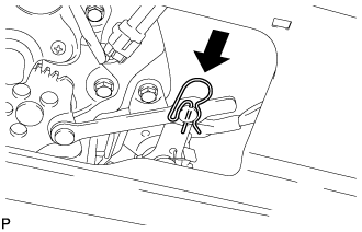
INSTALL PIN HOLD CLIP (w/ Easy Closer)
Install the pin hold clip.
11.
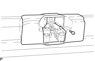
INSTALL BACK DOOR LOCK PROTECTOR (w/ Rear Bumper Step)
Install the back door lock protector with the screw.
12.
INSTALL BACK DOOR STOPPER BRACKET SUB-ASSEMBLY (for Rough Road Area Spec)
Install the back door stopper bracket sub-assembly with the 2 bolts.
13.
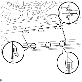
INSTALL BACK DOOR CLOSER COVER (w/ Easy Closer)
Attach the 3 claws and 3 clips to install the back door closer cover.
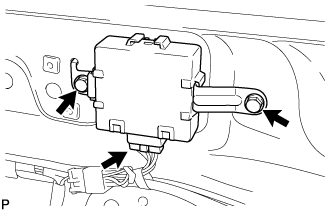
14.
INSTALL BACK DOOR CLOSER RELAY (w/ Easy Closer)
Install the back door closer relay with the 2 screws. Connect the connector.
15.
INSTALL TELEVISION CAMERA ASSEMBLY (w/ Rear View Monitor System)
Attach the 2 claws to install the rear television camera assembly.
Install the screw.
Connect the connector.
16.
INSTALL LICENSE PLATE LIGHT ASSEMBLY (w/o Smart Entry and Start System)
Install the 2 license plate lights to the back door outside garnish.
Attach the 2 wire harness clamps and install the 2 screws.
17.
INSTALL DOOR ELECTRICAL KEY SWITCH COVER (w/ Smart Entry and Start System)
Install the door electrical key switch cover.
18.
INSTALL LICENSE PLATE LIGHT ASSEMBLY (w/ Smart Entry and Start System)
Install the 2 license plate light assemblies (smart switch) to the back door outside garnish.
Attach the 2 wire harness clamps and install the 2 screws.
Install the license plate light assembly (smart switch) with the 2 screws.
19.
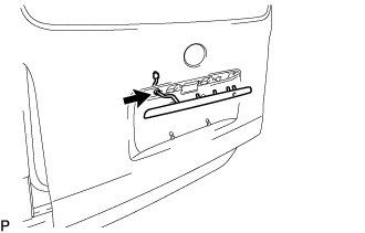
INSTALL BACK DOOR OUTSIDE GARNISH
Install the grommet. Attach the 2 clips to install the back door outside garnish.
Install the 5 nuts.
w/ Smart Entry and Start System:
Connect the 2 connectors.
w/o Smart Entry and Start System:
Connect the connector.
20.
INSTALL BACK DOOR OUTSIDE HANDLE
Install the back door outside handle with the 2 nuts.
21.
INSTALL BACK DOOR LOCK CYLINDER ASSEMBLY
Install the back door lock cylinder assembly with the 2 nuts.
22.
INSTALL BACK DOOR REMOTE CONTROL ASSEMBLY (w/o Power Door Lock)
Install the back door remote control assembly with the 2 screws.
Connect the wire and link.
Attach the clamp.
23.
INSTALL BACK DOOR REMOTE CONTROL ASSEMBLY (w/ Power Door Lock)
Install the back door remote control assembly with the 3 screws.
Connect the wire and link.
Attach the 2 clamps.
24.
INSTALL BACK DOOR INSIDE HANDLE ASSEMBLY (w/ Back Door Inside Handle)
Install the back door inside handle assembly with the 3 screws.
Connect the link.
Text in Illustration
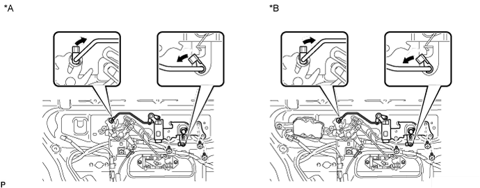
*A
w/o Power Door Lock
*B
w/ Power Door Lock
25.
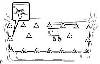
INSTALL BACK DOOR TRIM BOARD (for Molded Door Trim)
Attach the 18 clips to install the back door trim board. Install the 2 screws.
26.
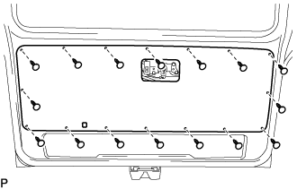
INSTALL BACK DOOR TRIM BOARD (for Board)
Install the back door trim board with the 16 clips.
27.
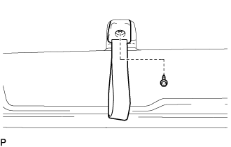
INSTALL BACK DOOR PULL STRAP (w/ Strap)
Install the back door pull strap with the screw.
28.
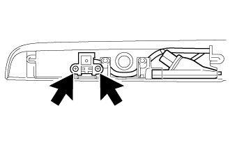
INSTALL BACK DOOR INSIDE HANDLE BEZEL (w/ Back Door Inside Handle Bezel)
w/o Illumination:
Install the back door inside handle bezel with the 2 screws.
w/ Illumination:
Connect the connector.
Install the back door inside handle bezel with the 2 screws.
Text in Illustration
*A
w/o Illumination:
*B
w/ Illumination:
29.
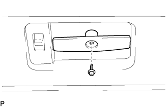
INSTALL BACK DOOR INSIDE HANDLE ASSEMBLY (w/ Back Door Inside Handle)
Install the back door inside handle assembly with the screw.
30.
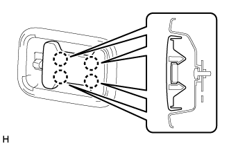
INSTALL BACK DOOR INSIDE HANDLE COVER (w/ Cover)
Attach the 4 claws to install the back door inside handle cover.
31.
INSTALL NO. 1 REAR WINDOW WIRE
Attach the 2 clamps to install the No. 1 rear window wire.
32.
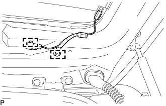
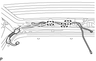
INSTALL NO. 3 BACK DOOR WIRE
Pass the end of the back door wire into the cabin, and connect it to the connector.
Attach the 3 clamps to install the No. 3 back door wire.
33.
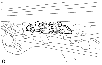
INSTALL HIGH MOUNTED STOP LIGHT ASSEMBLY (w/ High Mounted Stop Light)
Install a new gasket to the high mounted stop light assembly.
Attach the 8 claws to install the high mounted stop light assembly. Connect the connector.
34.
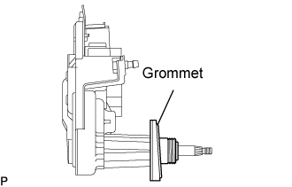
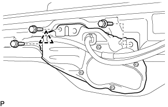
INSTALL REAR WIPER MOTOR ASSEMBLY (w/ Rear Wiper)
Install the grommet as shown in the illustration.
Install the rear wiper motor with the 3 bolts.
Torque:
5.4 N*m{
55 kgf*cm
, 48 in.*lbf
}
Install the clamp and connect the connector.
35.
INSTALL NO. 1 REAR WIPER LINK PIVOT WASHER (w/ Rear Wiper)
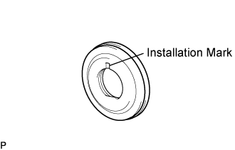
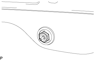
Install the rear No.1 wiper link pivot washer from the outside of the vehicle with the installation mark at the top.
Using the socket wrench (27 mm), install the lock nut.
Torque:
12 N*m{
120 kgf*cm
, 9 ft.*lbf
}
NOTICE:
Do not damage the glass.
36.
INSTALL REAR WIPER SHAFT COVER (w/ Rear Wiper)
37.
INSTALL REAR WIPER ARM AND BLADE ASSEMBLY (w/ Rear Wiper)
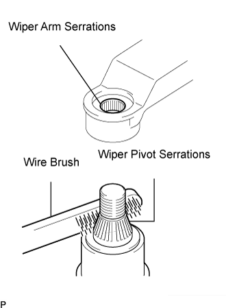
Operate the wiper, and stop the rear wiper motor at the automatic stop position. Clean the wiper arm serrations.
Clean the wiper pivot serrations with a wire brush (when reinstalling).
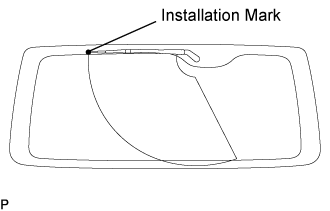
Install the rear wiper arm and blade assembly with the nut at the position as shown in the illustration.
Torque:
9.8 N*m{
100 kgf*cm
, 87 in.*lbf
}
HINT:
Hold the arm hinge by hand to fasten the nut.
Operate the rear wiper while spraying water or washer fluid on the windshield. Make sure that the wipers function properly and there is no interference with the vehicle body.
38.
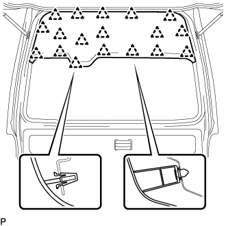
INSTALL UPPER BACK DOOR TRIM BOARD ASSEMBLY (for Wide Body)
Attach the 18 clips to install the upper back door trim board assembly.
39.
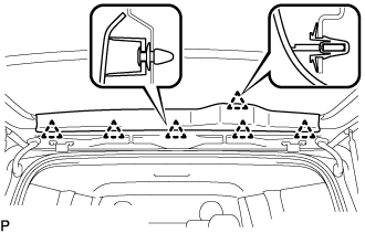
INSTALL UPPER BACK DOOR TRIM BOARD ASSEMBLY (w/ Rear Wiper)
Attach the 6 clips to install the upper back door trim board assembly.
40.
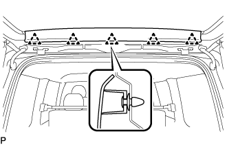
INSTALL UPPER BACK DOOR TRIM BOARD ASSEMBLY (w/o Rear Wiper)
Attach the 5 clips to install the upper back door trim board assembly.
41.
INSTALL BACK DOOR SERVICE HOLE COVER (for Wide Body)
42.
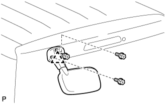
INSTALL OUTER UNDER REAR VIEW MIRROR ASSEMBLY (w/ Outer Under Rear View Mirror)
Install the outer under rear view mirror with the 3 screws and the pin.
Torque:
10 N*m{
102 kgf*cm
, 7 ft.*lbf
}
43.
INSPECT AND ADJUST BACK DOOR
(Click here )