REMOVAL
Removal / installation · Vehicles built Jan 2015 – Mar 2016
Versions by build date: Oct 2014 – Dec 2014 Jan 2015 – Mar 2016 Apr 2016 – Dec 2016 from Jan 2017
| 1. DISCHARGE FUEL SYSTEM PRESSURE |

Check that the battery positive voltage is above 12 V.
Discharge the fuel system pressure (Click here).
Disconnect the negative terminal cable from the battery.
Pinch and pull the No. 1 fuel hose (fuel tube connector) to disconnect it from the fuel pressure pulsation damper assembly.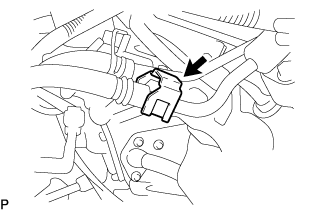

- CAUTION:
- Always read the precautions (Click here) before disconnecting the fuel tube connector (quick type).
- The fuel tube may spray fuel as a result of pressure that remains in it. Do not allow fuel to be sprayed in the engine compartment.
- Always read the precautions (Click here) before disconnecting the fuel tube connector (quick type).
Install SST (pressure gauge) as shown in the illustration.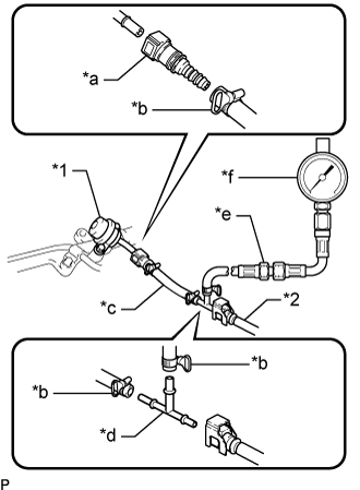
- SST
- 09268-45101
(09268-41250, 09268-41260, 09268-41280, 09268-41500, 09268-41700, 95336-08070)
Text in Illustration *1
Fuel Pressure Pulsation Damper Assembly
*2
No. 1 Fuel Hose
*a
SST (Fuel Tube Connector)
*b
SST (Hose Band)
*c
SST (Hose)
*d
SST (T-Joint)
*e
SST (Hose Joint)
*f
SST (Pressure Gauge)
Wipe off any gasoline.
Reconnect the negative terminal cable.
Operate the fuel pump.
Connect the intelligent tester to the DLC3.
Turn the ignition switch to ON.
- NOTICE:
- Do not start the engine.
Turn the intelligent tester on.
Enter the following menus: Powertrain / Engine and ECT / Active Test / Control the Fuel Pump / Speed.
Measure the fuel pressure.
- Standard fuel pressure:
- 281 to 287 kPa (2.87 to 2.93 kgf/cm2, 40.8 to 41.7 psi)
If the pressure is lower than the specification, check the fuel hoses and connections, fuel pump, fuel filter assembly and fuel pressure regulator assembly.
Start the engine.
Measure the fuel pressure.
- Standard fuel pressure:
- 281 to 287 kPa (2.87 to 2.93 kgf/cm2, 40.8 to 41.7 psi)
Stop the engine.
Check that the fuel pressure remains as specified for 5 minutes after the engine has stopped.
- Standard fuel pressure:
- 147 kPa (1.5 kgf/cm2, 21 psi) or more
After checking the fuel pressure, disconnect the negative terminal cable and carefully remove SST and the fuel tube connector to prevent gasoline from spraying.
Reconnect the No. 1 fuel hose (fuel tube connector) to the fuel pressure pulsation damper assembly.
| 2. PRECAUTION |
- NOTICE:
- After turning the ignition switch off, waiting time may be required before disconnecting the cable from the battery terminal. Therefore, make sure to read the disconnecting the cable from the battery terminal notice before proceeding with work (Click here).
| 3. DISCONNECT CABLE FROM NEGATIVE BATTERY TERMINAL |
- NOTICE:
- When disconnecting the cable, some systems need to be initialized after the cable is reconnected (Click here).
| 4. REMOVE THROTTLE BODY ASSEMBLY |
| 5. DISCONNECT NO. 1 FUEL HOSE |
Disconnect the No. 1 fuel hose from the fuel pressure pulsation damper assembly (Click here).
| 6. REMOVE FUEL DELIVERY PIPE SUB-ASSEMBLY |
- NOTICE:
- Be careful not to drop the fuel injector assemblies when removing the fuel delivery pipe sub-assembly.
Disconnect the vacuum hose from the fuel pressure regulator assembly.
Slide the clamp and disconnect the No. 2 fuel hose from the fuel pressure regulator assembly.
Disconnect the 4 fuel injector connectors.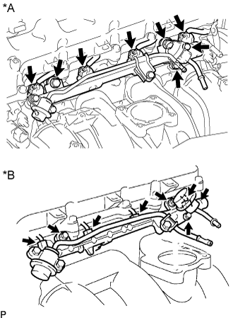
Text in Illustration *A
w/ Dual VVT-i
*B
w/o Dual VVT-i
Remove the 2 bolts, fuel pulsation damper assembly and O-ring.
Remove the 2 bolts and fuel delivery pipe sub-assembly together with the 4 fuel injector assemblies.
- NOTICE:
- Be careful not to drop the fuel injector assemblies when removing the fuel delivery pipe sub-assembly.
Remove the 2 No. 1 delivery pipe spacers from the cylinder head sub-assembly.
Remove the 4 injector vibration insulators.
Using a screwdriver, pry out the 4 injector spacers and 4 O-rings from the cylinder head sub-assembly.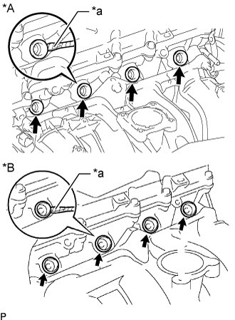
Text in Illustration *A
w/ Dual VVT-i
*B
w/o Dual VVT-i
*a
Protective Tape
- HINT:
- Tape the screwdriver tip before use.
| 7. REMOVE FUEL INJECTOR ASSEMBLY |
Pull out the 4 fuel injector assemblies from the fuel delivery pipe sub-assembly.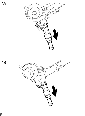
Text in Illustration *A
w/ Dual VVT-i
*B
w/o Dual VVT-i

Pull Out
Remove the O-rings from the fuel injector assemblies.