INSTALLATION
Removal / installation · Vehicles built from Jan 2017
Versions by build date: Oct 2014 – Dec 2014 Jan 2015 – Mar 2016 Apr 2016 – Dec 2016 from Jan 2017
- HINT:
- Use the same procedure for the RH and LH sides.
- The procedure listed below is for the LH side.
- Use the same procedure for the RH and LH sides.
| 1. INSTALL FRONT AIRBAG SENSOR LH |

Check that the ignition switch is off.
Check that the cable is disconnected from the negative (-) battery terminal.
- CAUTION:
- Wait at least 90 seconds after disconnecting the cable from the negative (-) battery terminal to disable the SRS system.
Connect the connector.
Install the front airbag sensor LH with the 2 bolts.
- Torque:
- 9.0 N*m{ 92 kgf*cm , 80 in.*lbf }
- NOTICE:
- If the front airbag sensor LH has been dropped, or there are any cracks, dents or other defects in the case or connector, replace it with a new one.
- When installing the front airbag sensor LH, be careful that the SRS wiring does not interfere with or is not pinched between other parts.
- If the front airbag sensor LH has been dropped, or there are any cracks, dents or other defects in the case or connector, replace it with a new one.
Check that there is no looseness in the installation parts of the front airbag sensor LH.
| 2. INSTALL UPPER RADIATOR SUPPORT SUB-ASSEMBLY |
Install the upper radiator support sub-assembly with the 6 bolts.
- Torque:
- 5.5 N*m{ 56 kgf*cm , 49 in.*lbf }
Attach the 2 clamps to connect the hood lock control cable assembly to the upper radiator support sub-assembly.
Connect the water by-pass hose to the radiator assembly, and slide the hose clamp to secure the hose.
| 3. INSTALL HOOD LOCK SUPPORT BRACE SUB-ASSEMBLY |
Install the hood lock support brace sub-assembly with the 3 bolts.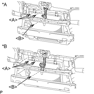

Text in Illustration *A
for Standard Body
*B
for Wide Body
- Torque:
- for bolt A:
- 5.5 N*m{ 56 kgf*cm , 49 in.*lbf }
- for bolt B:
- 12 N*m{ 122 kgf*cm , 9 ft.*lbf }
| 4. INSTALL HOOD LOCK ASSEMBLY |
Connect the hood lock control cable assembly to the hood lock assembly.
Install the hood lock assembly with the 3 bolts.
- Torque:
- 12 N*m{ 122 kgf*cm , 9 ft.*lbf }
| 5. INSTALL WINDSHIELD WASHER MOTOR AND PUMP ASSEMBLY |
- for 1TR-FE (Click here)
- for 2TR-FE (Click here)
- for 1KD-FTV (Click here)
- for 2KD-FTV (Click here)
- for 5L-E (Click here)
| 6. INSTALL RADIATOR RESERVE TANK ASSEMBLY |
Install the radiator reservoir assembly with the bolt.
- Torque:
- 8.0 N*m{ 82 kgf*cm , 71 in.*lbf }
Connect the No. 2 water by-pass hose to the radiator reservoir assembly, and slide the hose clamp to secure the hose.
Connect the water by-pass hose to the radiator reservoir assembly, and slide the hose clamp to secure the hose.
| 7. INSTALL FRONT BUMPER COVER |
Attach the 14 claws and 2 guides to install the front bumper cover.
Install the 3 bolts and 6 clips.
w/ Fog Light:
Connect the No. 4 engine room wire connector.
| 8. INSTALL STEP PLATE COVER RH |
- HINT:
- Use the same procedure described for the LH side.
| 9. INSTALL STEP PLATE COVER LH |
Attach the claw to install the step plate cover LH.
Install the 4 clips.
| 10. INSTALL RADIATOR GRILLE |
Attach the 8 claws to install the radiator grille.
Install the 4 clips and 2 screws.
| 11. INSTALL NO. 1 AIR INLET DUCT (w/ Intercooler) |
- for 1KD-FTV (Click here)
- for 2KD-FTV (Click here)
| 12. INSTALL UPPER RADIATOR SUPPORT SEAL (w/o Intercooler) |
- for 1TR-FE (Click here )
- for 2TR-FE (Click here)
- for 2KD-FTV (Click here)
- for 5L-E (Click here)
| 13. ADD ENGINE COOLANT |
- for 1TR-FE (Click here)
- for 2TR-FE (Click here)
- for 1KD-FTV (Click here)
- for 2KD-FTV (Click here)
- for 5L-E (Click here)
| 14. CONNECT CABLE TO NEGATIVE BATTERY TERMINAL |
- NOTICE:
- When disconnecting the cable, some systems need to be initialized after the cable is reconnected (Click here).
| 15. PERFORM DIAGNOSTIC SYSTEM CHECK |
| 16. CHECK SRS WARNING LIGHT |