DISASSEMBLY
Removal / installation · Vehicles built from Oct 2014
| 1. REMOVE FRONT DISC BRAKE PAD KIT |

Remove the 2 brake pads with anti-squeal shims.
| 2. REMOVE FRONT DISC BRAKE ANTI SQUEAL SHIM KIT |
Remove the 4 anti-squeal shims from the brake pad.
Remove the pad wear indicator from each pad.
| 3. REMOVE FRONT DISC BRAKE PAD SUPPORT PLATE |
| 4. REMOVE FRONT DISC BRAKE PAD SUPPORT PLATE |
| 5. REMOVE FRONT DISC BRAKE CYLINDER SLIDE PIN |
Remove the cylinder slide pin from the cylinder mounting.
| 6. REMOVE FRONT DISC BRAKE CYLINDER SLIDE BUSH |
Using a screwdriver, remove the cylinder slide bush from the cylinder slide pin.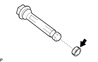

- HINT:
- Tape the screwdriver tip before use.
| 7. REMOVE FRONT DISC BRAKE CYLINDER SLIDE PIN NO.2 |
Remove the cylinder slide pin No.2 from the cylinder mounting.
| 8. REMOVE FRONT DISC BRAKE CYLINDER MOUNTING |
Remove the 2 bolts and cylinder mounting.
| 9. REMOVE BUSH DUST BOOT NO.1 |
Secure the cylinder mounting in a vise.
Using a screwdriver and a plastic hammer, remove the 2 bush dust boots.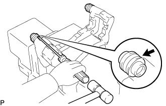
| 10. REMOVE CYLINDER BOOT |
Using a screwdriver, remove the set ring.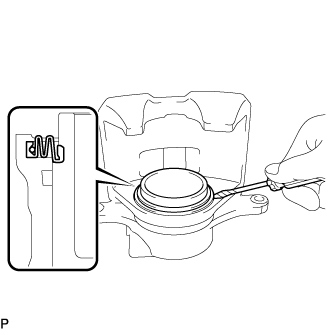
- NOTICE:
- Do not damage the inner cylinder or cylinder groove.
- HINT:
- Tape the screwdriver tip before use.
Remove the cylinder boot.
| 11. REMOVE FRONT DISC BRAKE PISTON |
Place a shop rag or a piece of cloth between the piston and the disc brake cylinder assembly.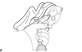
Use compressed air to remove the piston from the disc brake cylinder assembly.
- CAUTION:
- Do not place your fingers in front of the piston when using compressed air.
- NOTICE:
- Do not spatter the brake fluid.
| 12. REMOVE PISTON SEAL |
Using a screwdriver, remove the piston seal from the disc brake cylinder assembly.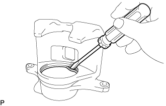
- HINT:
- Tape the screwdriver tip before use.
| 13. REMOVE FRONT DISC BRAKE BLEEDER PLUG CAP |
| 14. REMOVE FRONT DISC BRAKE BLEEDER PLUG |
| 15. SEPARATE FRONT SPEED SENSOR |
Remove the 2 bolts, and separate the speed sensor from the steering knuckle.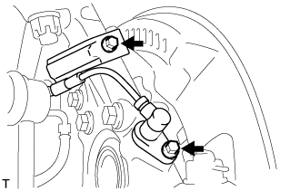
- NOTICE:
- Be careful not to damage the speed sensor.
- Prevent foreign matter from adhering to the speed sensor.
- Be careful not to damage the speed sensor.
| 16. SEPARATE TIE ROD END SUB-ASSEMBLY |
Remove the cotter pin and castle nut.
Using SST, separate the tie rod end from the steering knuckle.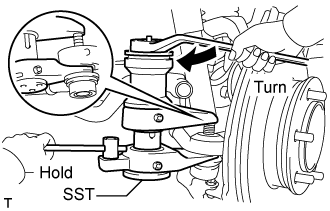
- SST
- 09628-00011
- NOTICE:
- Do not damage the ball joint dust boot.
- Do not damage the brake dust cover.
- Make sure that the string of the SST is securely tied to the vehicle.
- Do not damage the ball joint dust boot.
| 17. REMOVE FRONT AXLE ASSEMBLY |
Remove the 4 bolts, 4 nuts and front axle assembly from the front suspension lower arm.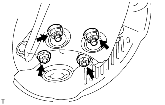
Remove the cotter pin and castle nut.
Using SST, remove the front axle assembly from the front suspension upper arm.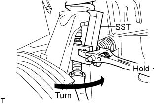
- SST
- 09628-62011
- NOTICE:
- Do not damage the ball joint dust boot.
- Apply grease to the threads and tip of the SST center bolt before use.
- Make sure that the string of the SST is securely tied to the vehicle.
- Do not damage the ball joint dust boot.
| 18. REMOVE FRONT LOWER BALL JOINT ASSEMBLY |
Fix the steering knuckle in the vise using aluminium plates.
- NOTICE:
- Do not damage the steering knuckle.
Remove the cotter pin.
Loosen the nut.
Using SST, separate the front lower ball joint assembly from the steering knuckle.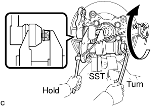
- SST
- 09628-00011
- NOTICE:
- Do not damage the ball joint dust boot.
- Make sure that the string of the SST is securely tied to the steering knuckle.
- Do not damage the ball joint dust boot.
Remove the nut and front lower ball joint assembly.
| 19. REMOVE INNER KNUCKLE GREASE RETAINER CAP (w/ Cap) |
Using a chisel, make a hole in the center of the outer knuckle grease retainer cap to insert a brass bar.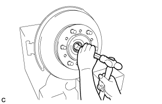
Using a brass bar, remove the inner knuckle grease retainer cap from the steering knuckle as shown in the illustration.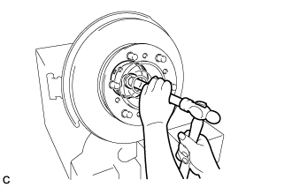
| 20. REMOVE OUTER KNUCKLE GREASE RETAINER CAP (w/ Cap) |
Using SST, remove the outer knuckle grease retainer cap.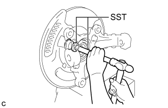
- SST
- 09950-60010
(09951-00300)
09950-70010 (09951-07200)
| 21. REMOVE STEERING KNUCKLE |
Remove the 4 bolts.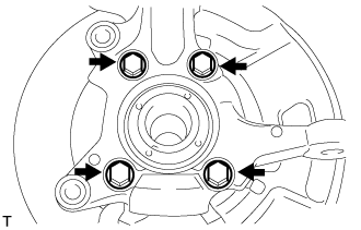
Using SST, remove the steering knuckle, brake dust cover from the front axle hub sub-assembly.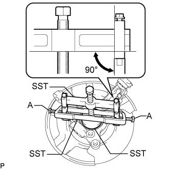
- SST
- 09950-40011
(09951-04020, 09952-04010, 09953-04010, 09958-04011)
09950-60010 (09951-00470)
09955-04140
09958-04030
- NOTICE:
- Apply grease to the threads and tip of the SST center bolt (09953-04010) before use.
- Make sure that the slide arm (09952-04010) is at a 90° angle to the hanger 200 (09951-04020) when using SST.
- Make sure that the claw No. 14 (09955-04140) is securely attached to the steering knuckle.
- Apply grease to the threads and tip of the SST center bolt (09953-04010) before use.
- HINT:
- For bolt A, use the bolt for the holder (09958-04011).
| 22. REMOVE FRONT DISC |
Remove the 6 bolts.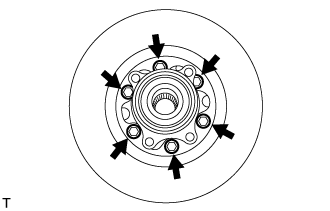
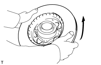
Remove the front disc as shown in the illustration.