REASSEMBLY
Removal / installation · Vehicles built from Oct 2014
- HINT:
- Use the same procedure for RHD and LHD vehicles.
- The procedure listed below is for LHD vehicles.
- Use the same procedure for the RH and LH sides.
- The procedure listed below is for the LH side.
- Use the same procedure for RHD and LHD vehicles.
| 1. INSTALL OUTER MIRROR RETRACTOR LH (w/ Retract Mirror) |

Install the actuator sub-assembly.
Attach the 2 claws to connect the 2 connectors of a new wire harness sub-assembly as shown in the illustration.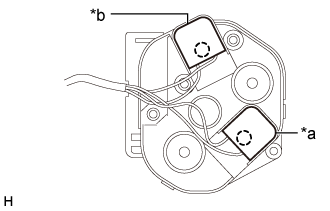

Text in Illustration *a
Black
*b
Gray
Install the actuator sub-assembly with the 3 screws.
Pull the wire harness sub-assembly through the frame sub-assembly as shown in the illustration.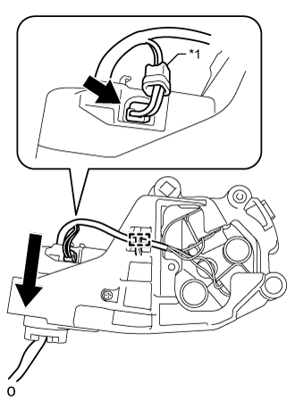
Connect the connector to install the rubber cover.
Text in Illustration *1
Rubber Cover
Attach the wire harness sub-assembly to the clamp.
Install the body sub-assembly with the 4 screws.
Using a T25 "TORX" socket wrench, install the base plate with a new "TORX" screw.
- Torque:
- 3.8 N*m{ 39 kgf*cm , 34 in.*lbf }
Install the base sub-assembly.
Using a T25 "TORX" socket wrench, install the base sub-assembly with 3 new "TORX" screws.
- Torque:
- 3.8 N*m{ 39 kgf*cm , 34 in.*lbf }
Attach the 5 claws to install a new gasket.
Align the mark of the wire harness sub-assembly with the end of the protrusion of the gasket into which the wire harness is inserted, and then secure the wire harness with tape as shown in the illustration.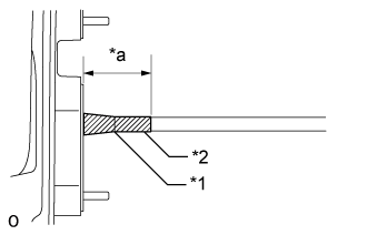
- NOTICE:
- Wrap at least 2 layers of tape around the wire harness.
- Make sure there is no gap between the tape and wire harness when applying tape.
- Wrap at least 2 layers of tape around the wire harness.
Text in Illustration *1
Mark
*2
Tape
*a
40 to 50 mm
Install the clamp.
Align the clamp with the mark and secure it with tape as shown in the illustration.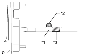
Text in Illustration *1
Mark
*2
Clamp
*3
Tape
Assemble the connector.
While referring to the chart below, insert the pins of the wire harness sub-assembly into the back of a new adapter until they lock.
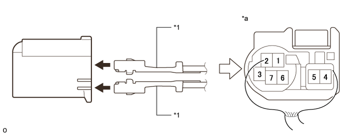
Text in Illustration *1
Wire Harness Pin
-
-
*a
Rear View of Connector
-
-
- NOTICE:
- When inserting the pins of the wire harness, compare a new connector with the connector that was cut off during removal and make sure that the arrangement of the wire colors of the pins is the same as before.
- Confirm that the pins of the wire harness are securely locked and cannot be pulled out.
- When a pin of the wire harness is locked, it cannot be pulled out. Therefore, be sure to insert each pin into the correct location.
- When inserting the pins of the wire harness, compare a new connector with the connector that was cut off during removal and make sure that the arrangement of the wire colors of the pins is the same as before.
- Wire Harness Color Chart:
for LH: 1
2
3
4
5
6
7
Blue
Green
Purple
-
-
Brown
Red
for RH: 1
2
3
4
5
6
7
Blue
Green
Purple
-
-
Brown
Red
| 2. INSTALL OUTER MIRROR LH (w/ Retract Mirror) |
Attach the 2 guides and 2 claws to install the outer mirror LH.