TERMINALS OF ECU
System information · Vehicles built from Oct 2014
| POWER WINDOW MASTER SWITCH |


Disconnect the K5 (L5) switch with the K5 (L5) switch connector still connected.
Measure the voltage according to the value(s) in the table below.
Symbols (Terminal No.)
Wiring Color
Terminal Description
Condition
Specified Condition
VCC (3) - SGND (2)
W - BR
Power supply
Ignition switch ON, power window master switch OFF → UP (Manual/Auto) or OFF → DOWN (Manual/Auto)
Below 1 V → 10 to 14 V
U (4) - GND (1)
Y - W-B
Power window motor UP output
Ignition switch ON, power window master switch OFF → UP (Manual/Auto)
Below 1 V → 10 to 14 V
B (6) - GND (1)
L - W-B
+B (B) power supply
Ignition switch ON
10 to 14 V
BW (7) - GND (1)
R - W-B
+B (BW) power supply
Constant
10 to 14 V
D (9) - GND (1)
G - W-B
Power window motor DOWN output
Ignition switch ON, power window master switch OFF → DOWN (Manual/Auto)
Below 1 V → 10 to 14 V
DCTY (11) - GND (1)
R - W-B
Door courtesy switch signal
Driver side door OPEN → CLOSE
10 to 14 V → Below 1 V
U (13) - GND (1)
L - W-B
Power window motor UP output (Remote)
Ignition switch ON, power window master switch OFF → UP (Remote)
Below 1 V → 10 to 14 V
PLS (14) - SGND (2)
L - BR
Power window motor sensor signal
Power window operating
Pulse generation
D (15) - GND (1)
R-L - W-B*1
R - W-B*2
Power window motor DOWN output (Remote)
Ignition switch ON, power window master switch OFF → DOWN (Remote)
Below 1 V → 10 to 14 V
PLS2 (17) - SGND (2)
Y - BR
Power window motor sensor signal
Power window operating
Pulse generation
- *1: for LHD
- *2: for RHD
- *1: for LHD
Disconnect the K5 (L5) switch connector.
Measure the voltage according to the value(s) in the table below.
Symbols (Terminal No.)
Wiring Color
Terminal Description
Condition
Specified Condition
GND (1) - Body ground
W-B - Body ground
Ground
Constant
Below 1 Ω
| POWER WINDOW SWITCH |

Disconnect the L6 (K6) switch with the L6 (K6) switch connector still connected.
Measure the voltage according to the value(s) in the table below.
Symbols (Terminal No.)
Wiring Color
Terminal Description
Condition
Specified Condition
D (1) - Body ground
G - Body ground
Power window motor DOWN output
Ignition switch ON, power window switch OFF → DOWN
Below 1 V → 10 to 14 V
SD (2) - Body ground
R-L - Body ground*1
R - Body ground*2
Power window motor DOWN output (Remote)
Ignition switch ON, power window master switch OFF → DOWN (Remote)
Below 1 V → 10 to 14 V
U (3) - Body ground
Y - Body ground
Power window motor UP output
Ignition switch ON, power window switch OFF → UP
Below 1 V → 10 to 14 V
B (4) - Body ground
L - Body ground
+B (B) power supply
Ignition switch ON
10 to 14 V
SU (5) - Body ground
L - Body ground
Power window motor UP output (Remote)
Ignition switch ON, power window master switch OFF → UP (Remote)
Below 1 V → 10 to 14 V
- *1: for LHD
- *2: for RHD
- *1: for LHD
| INSTRUMENT PANEL JUNCTION BLOCK |
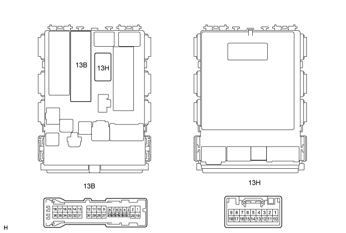
| Symbols (Terminal No.) |
Wiring Color |
Terminal Description |
Condition |
Specified Condition |
| B (13B-36) - Body ground |
W-L - Body ground |
+B (B) power supply |
Ignition switch ON |
10 to 14 V |
| BW (13H-1) - Body ground |
W-R - Body ground |
+B (BW) power supply |
Always |
10 to 14 V |