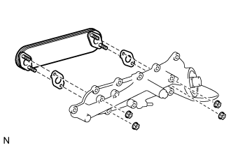
REMOVAL
Removal / installation · Vehicles built from Oct 2014
| 1. DISCONNECT CABLE FROM NEGATIVE BATTERY TERMINAL |
| 2. REMOVE ENGINE UNDER COVER NO.1 (w/ Engine Under Cover No.1) |
| 3. DRAIN ENGINE COOLANT |

- CAUTION:
- Do not remove the radiator reservoir cap sub-assembly while the engine and radiator are still hot. Pressurized, hot engine coolant and steam may be released and cause serious burns.
Loosen the radiator drain cock plug.
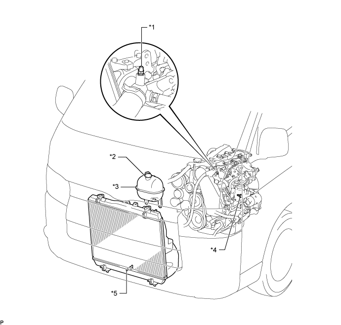

Text in Illustration *1
Bleeder Plug
*2
Radiator Reservoir Cap Sub-assembly
*3
Radiator Reservoir Assembly
*4
Cylinder Block Drain Cock Plug
*5
Radiator Drain Cock Plug
-
-
Remove the radiator reservoir cap sub-assembly.
Loosen the cylinder block drain cock plug (on the engine oil cooler cover), and drain the engine coolant.
Tighten the radiator drain cock plug.
Tighten the cylinder block drain cock plug (on the engine oil cooler cover).
- Torque:
- 8.0 N*m{ 82 kgf*cm , 71 in.*lbf }
| 4. REMOVE BATTERY SERVICE HOLE COVER |
| 5. REMOVE FRONT SEAT ASSEMBLY RH (for Hi-back Seat Type) |
- HINT:
- Use the same procedures described for the LH side. (Click here)
| 6. REMOVE FRONT SEAT ASSEMBLY RH (for Low-back Seat Type) |
- HINT:
- Use the same procedures described for the LH side. (Click here)
| 7. REMOVE FRONT DOOR SCUFF PLATE RH |
| 8. REMOVE ENGINE SERVICE HOLE SUB COVER SUB-ASSEMBLY |
Roll up the carpet.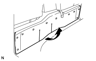
Remove the 3 bolts and the engine service hole cover No.2.
| 9. REMOVE FAN & GENERATOR V BELT |
Remove the drive belt by rotating the tensioner pulley in clockwise direction to loosen its tension with the pulley set bolt of the tensioner.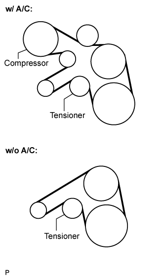
| 10. REMOVE TIMING BELT COVER NO.1 |
Remove the wire harness clamp.
Remove the 6 bolts and timing belt cover No.1.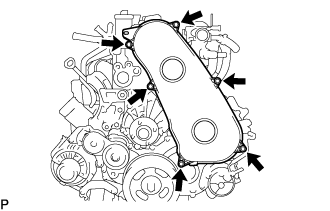
| 11. REMOVE TIMING BELT |
Turn the crankshaft in the clockwise direction and align the timing marks as shown in the illustration.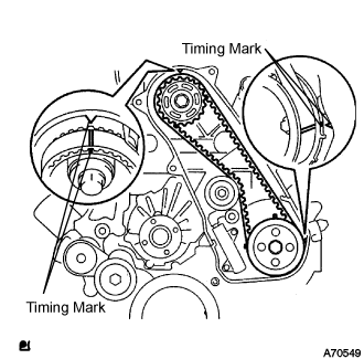
Uniformly loosen the 2 bolts, and remove the chain tensioner assembly No.1.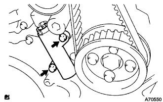
Remove the timing belt.
| 12. SEPARATE VANE PUMP OIL RESERVOIR ASSEMBLY |
Remove the 2 bolts. Separate the vane pump oil reservoir assembly.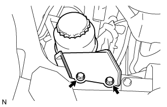
| 13. SEPARATE OIL RETURN HOSE (w/ Intercooler) |
Loosen the clip.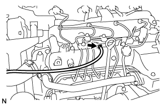
Disconnect the oil return hose from the intake manifold.
| 14. REMOVE EGR PIPE SUB-ASSEMBLY NO.1 (w/ EGR Valve) |
Disconnect the fuel pressure sensor connector.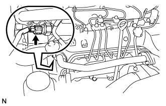
Remove the 2 bolts, 2 nuts, and the EGR pipe sub-assembly.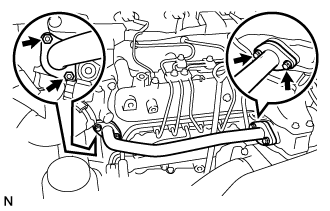
Remove the 2 gaskets.
| 15. REMOVE AIR HOSE NO.4 |
Loosen the 2 clamps.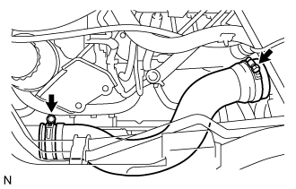
Remove the air hose No.4.
| 16. REMOVE DIESEL THROTTLE BODY ASSEMBLY |
Disconnect the 2 throttle body connectors.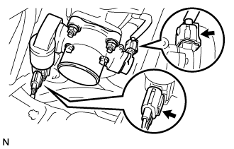
Remove the 2 bolts, 2 nuts, and the diesel throttle body assembly.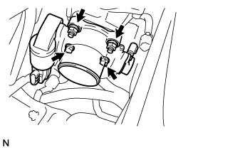
Remove the gasket from intake air connector.
| 17. REMOVE ENGINE SERVICE HOLE COVER NO.2 |
Roll up the carpet.
Remove the 3 bolts and the engine service hole cover No.2.
| 18. REMOVE INTAKE AIR CONNECTOR (w/o EGR Valve) |
Remove the bolt, and separate the manifold stay.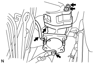
Disconnect the vacuum hose from intake air connector.
Remove the bolt, 2 nuts and the intake air connector assembly.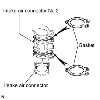
Remove the 2 gaskets and intake air connector No.2 from the intake air connector.
| 19. REMOVE ELECTRIC EGR CONTROL VALVE ASSEMBLY (w/ EGR Valve) |
Remove the vacuum regulating valve.
Remove the 2 vacuum hoses and the vacuum regulating valve connector.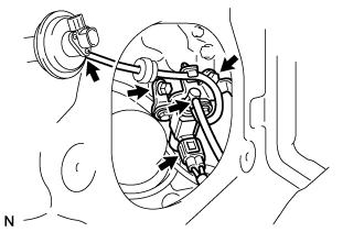
Remove the 2 bolts and the vacuum regulating valve.
Remove the EGR valve assembly with the sensor.
Remove the bolt, and separate the manifold stay.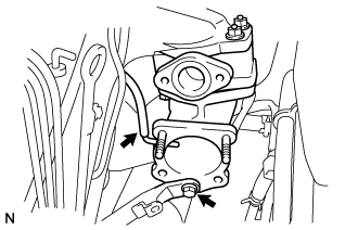
Disconnect the vacuum hose from the intake air connector.
Disconnect the intake air temperature sensor connector.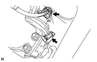
Disconnect the EGR valve position sensor connector.
Remove the bolt, 2 nuts and the intake air connector assembly.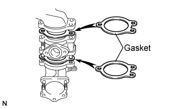
Remove the 2 gaskets and EGR valve assembly from the intake air connector.
| 20. REMOVE OIL LEVEL GAUGE GUIDE |
Remove the oil level gauge.
Remove the bolt and oil level gauge guide.
| 21. REMOVE INJECTION PIPE SUB-ASSEMBLY |
- SST
- 09023-12701
Remove the injection pipe.
Remove the 2 nuts and injection pipe clamp No.3.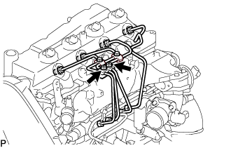
Using SST, remove the 4 injection pipes.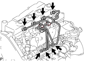
- SST
- 09023-12701
| 22. REMOVE FUEL INLET PIPE SUB-ASSEMBLY |
Using SST, remove the fuel inlet pipe sub-assembly.
- SST
- 09023-12701
| 23. REMOVE NOZZLE LEAKAGE PIPE ASSEMBLY NO.2 |
Disconnect 3 fuel hoses from nozzle leakage pipe assembly No.2.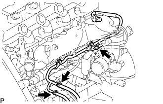
Remove the union bolt from nozzle leakage pipe No.2.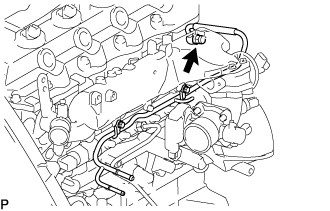
Remove the 2 bolts and nozzle leakage pipe No.2.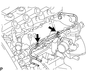
Remove the gasket from nozzle leakage pipe No.2.
| 24. REMOVE INTAKE MANIFOLD |
Remove the bolt, nut, and the manifold stay.
Remove the bolt, and disconnect the ground cable.
Remove the 4 bolts, 2 nuts, and intake manifold.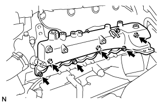
Remove the gasket from the cylinder head.
| 25. REMOVE OIL FILTER SUB-ASSEMBLY |
Using SST, remove the oil filter.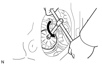
- SST
- 09228-07501
- HINT:
- Position the drain oil container to collect the oil from the oil filter.
| 26. REMOVE COMMON RAIL ASSEMBLY |
Disconnect the fuel pressure sensor connector from the common rail assembly.
Disconnect the fuel hose from the fuel pressure limiter.
Remove the 2 bolts and common rail assembly.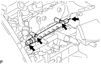
| 27. REMOVE INJECTION OR SUPPLY PUMP ASSEMBLY |
Remove the 4 bolts.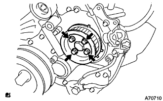
Remove the camshaft timing pulley flange No.2 and pump drive shaft pulley.
Using SST, remove the supply pump gear set nut and O-ring while holding the crankshaft pulley.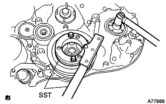
- SST
- 09213-58013
09330-00021
Disconnect the 2 fuel hoses.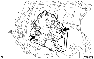
Disconnect the 2 connectors and wire harness.
Loosen the 2 nuts as shown in the illustration.
Using SST, disengage the supply pump from the supply pump gear.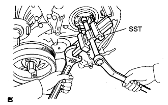
- SST
- 09950-50013
(09951-05010, 09952-05010, 09953-05020, 09954-05021)
Remove the 2 nuts and supply pump from the engine.
Remove the O-ring from the supply pump.
Remove the pulley key from the supply pump.
| 28. REMOVE OIL COOLER COVER SUB-ASSEMBLY (w/o EGR Valve) |
Disconnect the oil pressure switch connector.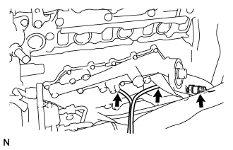
Disconnect the oil filter drain hoses.
Remove the 2 nuts, 13 bolts, oil cooler cover, and gasket.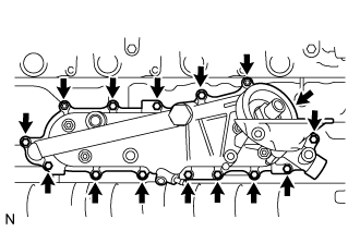
| 29. REMOVE OIL COOLER COVER SUB-ASSEMBLY (w/ EGR Valve) |
Disconnect the oil pressure switch connector.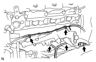
Disconnect the oil filter drain hoses.
Remove the 2 nuts and the vacuum transmitting pipe No.2 from the oil cooler cover.
Remove the 13 bolts, oil cooler cover, and gasket.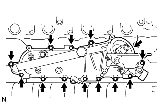
| 30. REMOVE OIL COOLER ASSEMBLY |
Loosen the 4 nuts until they are flush with the end of the bolts.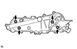
Using a plastic hammer, uniformly tap the end of the nuts to separate the oil cooler cover and oil cooler assembly.
Remove the 4 nuts, oil cooler assembly, and 2 gaskets from the oil cooler cover.