TC and CG Terminal Circuit
Circuit diagnosis · Vehicles built Oct 2014 – Dec 2014
DESCRIPTION
DTC output mode is set by connecting terminals TC and CG of the DLC3.The DTCs are displayed by blinking the SRS warning light.
WIRING DIAGRAM
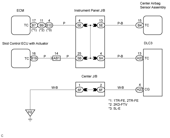

INSPECTION PROCEDURE
| 1. CHECK WIRE HARNESS (DLC3 - CENTER AIRBAG SENSOR ASSEMBLY) |

Turn the ignition switch to the LOCK position.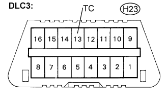
Disconnect the connectors from the center airbag sensor assembly.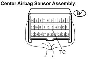
Measure the resistance according to the value(s) in the table below.
- Resistance:
Tester connection
Condition
Specified condition
H23-13 (TC) -
B4-15 (TC)
Always
Below 1 Ω
|
|
||||

| OK | |
 |
| 2. CHECK WIRE HARNESS (CG OF DLC3 - BODY GROUND) |
Measure the resistance according to the value(s) in the table below.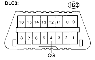
- Resistance:
Tester connection
Condition
Specified condition
H23-4 (CG) -
Body ground
Always
Below 1 Ω
|
|
||||
| OK | |
|
| 3. CHECK WIRE HARNESS (TC OF CENTER AIRBAG SENSOR ASSEMBLY) |
Measure the resistance according to the value(s) in the table below.
- Resistance:
Tester connection
Condition
Specified condition
B4-15 (TC) -
Body ground
Always
1 MΩ or higher
|
|
||||
| OK | ||
 |
||
| ||