C1249/49 Open in Stop Light Switch Circuit
Diagnostic trouble codes · Vehicles built Oct 2014 – Dec 2014
Versions by build date: Oct 2014 – Dec 2014 Jan 2015 – Dec 2016 from Jan 2017
DESCRIPTION
This skid control ECU inputs the stop light switch signal and detects the status of brake operation.The skid control ECU has an open detection circuit. If an open in the stop light switch input line or GND side stop light circuit is detected when the stop light switch is off, this DTC is output.
| DTC No. |
DTC Detection Condition |
Trouble Area |
| C1249/49 |
With the IG1 terminal voltage 9.5 V or more, open in the stop light switch circuit continues for 0.3 seconds or more. |
|
WIRING DIAGRAM
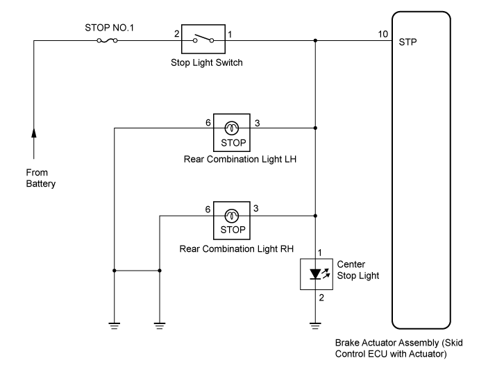

INSPECTION PROCEDURE
| 1. CHECK STOP LIGHT SWITCH OPERATION |

Check that the stop light comes on when the brake pedal is depressed, and goes off when the brake pedal is released.
- OK:
- Stop light switch function is normal.
- HINT:
- Check the stop light bulb as it may have burnt out.
|
|
||||

| OK | |
 |
| 2. INSPECT SKID CONTROL ECU (STP TERMINAL VOLTAGE) |
Disconnect the skid control ECU connector.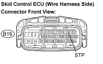
Measure the voltage according to the value(s) in the table below.
- Standard voltage:
Tester Connection
Condition
Specified Condition
B19-10 (STP) - Body ground
Stop light switch ON
(Brake pedal depressed)
8 to 16 V
B19-10 (STP) - Body ground
Stop light switch OFF
(Brake pedal released)
Below 1.5 V
- Result:
Condition
Proceed to
OK (When troubleshooting in accordance with the DTC CHART)
A
OK (When troubleshooting in accordance with the PROBLEM SYMPTOMS TABLE)
B
NG
C
|
|
||||
|
|
||||

| A | |
|
| 3. RECONFIRM DTC |
Clear the DTC (Click here).
Check that the same DTC is recorded (Click here).
- HINT:
- Reinstall the sensors, connectors, etc. and restore the vehicle to its prior condition before rechecking for DTCs.
- Result:
Condition
Proceed to
DTC (C1249/49) is output
A
DTC (C1249/49) is not output
B
|
|
||||
| A | ||
 |
||
| ||
| 4. INSPECT STOP LIGHT SWITCH (POWER SOURCE TERMINAL VOLTAGE) |
Disconnect the stop light switch connector.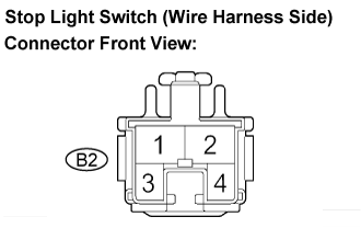
Measure the voltage according to the value(s) in the table below.
- Standard voltage:
Tester Connection
Condition
Specified Condition
B2-2 - Body ground
Always
10 to 14 V
|
|
||||
| OK | |
|
| 5. INSPECT STOP LIGHT SWITCH |
Measure the resistance according to the value(s) in the table below.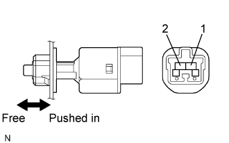
- Standard resistance:
Tester Connection
Condition
Specified Condition
1 - 2
Switch pin free
Below 1 Ω
1 - 2
Switch pin pushed in
10 kΩ or higher
|
|
||||
| OK | |
|
| 6. CHECK HARNESS AND CONNECTOR (BETWEEN SKID CONTROL ECU AND STOP LIGHT SWITCH) |
Disconnect the skid control ECU connector.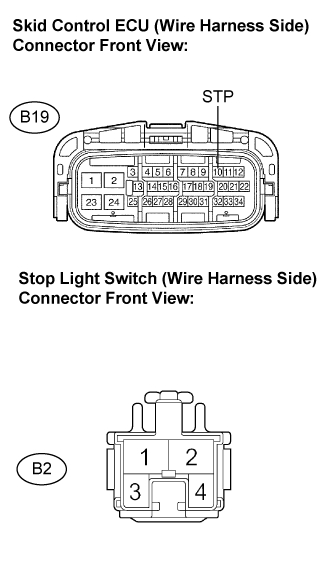
Measure the resistance according to the value(s) in the table below.
- Standard resistance:
Tester Connection
Specified Condition
B19-10 (STP) - B2-1
Below 1 Ω
B19-10 (STP) - Body ground
10 kΩ or higher
- HINT:
- When troubleshooting in accordance with the DTC CHART, check DTCs before replacing the brake actuator assembly (Click here).
- When troubleshooting in accordance with the PROBLEM SYMPTOMS TABLE, be sure to follow the table before replacing the brake actuator assembly (Click here).
- When troubleshooting in accordance with the DTC CHART, check DTCs before replacing the brake actuator assembly (Click here).
|
|
||||
| OK | ||
|
||
| ||