Home › BRAKE › BRAKE CONTROL › ANTI-LOCK BRAKE SYSTEMABS Warning Light Remains ON
Circuit diagnosis · Vehicles built Oct 2014 – Dec 2014
Versions by build date: Oct 2014 – Dec 2014 Jan 2015 – Dec 2016 from Jan 2017
DESCRIPTION
If any of the following is detected, the ABS warning light remains on.
The skid control ECU connectors are disconnected from the skid control ECU.
There is a malfunction in the skid control ECU internal circuit.
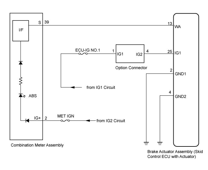
There is an open in the harness between the combination meter and the skid control ECU.
HINT:
In some cases, the intelligent tester cannot be used when the skid control ECU is abnormal.
WIRING DIAGRAM
INSPECTION PROCEDURE
1. INSPECT IF SKID CONTROL ECU CONNECTOR IS SECURELY CONNECTED
Check the skid control ECU connector's connecting condition.
OK:
The connector should be securely connected.
NG
OK
2. INSPECT BATTERY
Check the battery voltage.
Standard voltage:
11 to 14 V
NG
OK
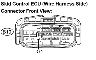
3. INSPECT SKID CONTROL ECU (IG1 TERMINAL VOLTAGE)
Disconnect the skid control ECU connector. Turn the ignition switch to the ON position.
Measure the voltage according to the value(s) in the table below.
Standard voltage:
Tester Connection
Specified Condition
B19-25 (IG1) - Body ground
10 to 14 V
NG
REPAIR OR REPLACE HARNESS OR CONNECTOR (IG1 CIRCUIT)
OK
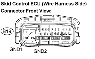
4. INSPECT SKID CONTROL ECU (GND TERMINAL CONTINUITY)
Turn the ignition switch off. Measure the resistance according to the value(s) in the table below.
Standard resistance:
Tester Connection
Specified Condition
B19-2 (GND1) - Body ground
Below 1 Ω
B19-24 (GND2) - Body ground
Below 1 Ω
NG
REPAIR OR REPLACE HARNESS OR CONNECTOR (GND CIRCUIT)
OK
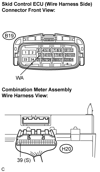
5. CHECK HARNESS AND CONNECTOR (BETWEEN SKID CONTROL ECU AND COMBINATION METER ASSEMBLY)
Disconnect the combination meter connector. Measure the resistance according to the value(s) in the table below.
Standard resistance:
Tester Connection
Specified Condition
B19-13 (WA) - H20-39 (S)
Below 1 Ω
B19-13 (WA) - Body ground
10 kΩ or higher
NG
REPAIR OR REPLACE HARNESS OR CONNECTOR
OK
6. INSPECT COMBINATION METER
Check the combination meter (Click here ).
HINT:
If troubleshooting has been carried out according to the PROBLEM SYMPTOMS TABLE, refer back to the table and proceed to the next step before replacing the part (Click here ).
NG
REPLACE COMBINATION METER ASSEMBLY
OK
REPLACE BRAKE ACTUATOR ASSEMBLY