INSPECTION
Inspection · Vehicles built from Oct 2014
| INSPECT TIMING BELT |
| INSPECT TIMING BELT IDLER SUB-ASSEMBLY NO.1 |
| INSPECT IDLER TENSION SPRING |
| INSPECT WATER PUMP ASSEMBLY |
| INSPECT OIL PUMP RELIEF VALVE |

Coat the valve with engine oil and check that it falls smoothly into the valve hole by its own weight.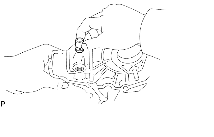

- If it does not fall smoothly into the valve hole, replace the relief valve. If necessary, replace the oil pump assembly.
- If it does not fall smoothly into the valve hole, replace the relief valve. If necessary, replace the oil pump assembly.
| INSPECT OIL PUMP DRIVE GEAR |
Install the rotors to the timing gear case sub-assembly with the rotors marks facing outward. Check that the rotors revolves smoothly.
Inspect the gear tip clearance.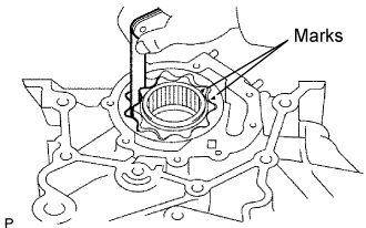
Using a feeler gauge, measure the clearance between the drive and driven gear tips.
- Standard tip clearance:
- 0.110 to 0.240 mm (0.0043 to 0.0094 in.)
- Maximum tip clearance:
- 0.30 mm (0.0118 in.)
- If the tip clearance is greater than the maximum, replace the gears as a set.
Inspect the gear body clearance.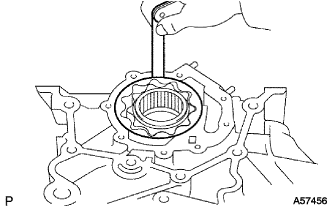
Using a feeler gauge, measure the clearance between the driven gear and timing gear case.
- Standard body clearance:
- 0.144 to 0.219 mm (0.0057 to 0.0086 in.)
- Maximum body clearance:
- 0.40 mm (0.0157 in.)
- If the body clearance is greater than the maximum, replace the gears as a set. If necessary, replace the oil pump assembly.
Inspect the gear side clearance.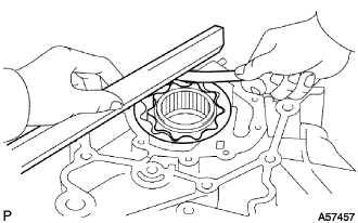
Using a feeler gauge and precision straight edge, measure the clearance between the gears and precision straight edge.
- Standard side clearance:
- 0.035 to 0.085 mm (0.0014 to 0.0033 in.)
- Maximum side clearance:
- 0.15 mm (0.0059 in.)
- If the side clearance is greater than the maximum, replace the gears as a set. If necessary, replace the oil pump assembly.