REASSEMBLY
Removal / installation · Vehicles built from Oct 2014
| 1. INSTALL OUTPUT SHAFT ASSEMBLY |

Apply gear oil to the sliding part of the output shaft assembly.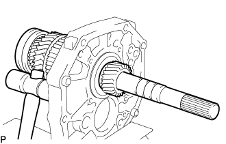

Using a plastic-faced hammer, install the output shaft assembly by tapping the intermediate plate.
| 2. INSTALL OUTPUT SHAFT BEARING SHAFT SNAP RING |
Using a snap ring expander, install the output shaft bearing shaft snap ring to the output shaft assembly.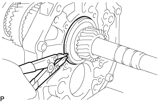
| 3. INSTALL INPUT SHAFT ASSEMBLY |
Apply gear oil to the input shaft assembly and No. 2 synchronizer ring, and install them to the output shaft assembly.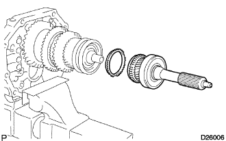
- NOTICE:
- Make sure that the No. 2 synchromesh shifting key fits into the grooves of the No. 2 synchronizer ring.
- Check that the input shaft assembly rotates smoothly.
- Make sure that the No. 2 synchromesh shifting key fits into the grooves of the No. 2 synchronizer ring.
| 4. INSTALL COUNTER GEAR |
Temporarily install the counter gear to the intermediate plate.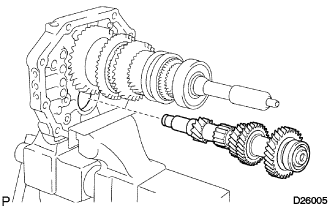
| 5. INSTALL COUNTER SHAFT CENTER BEARING |
Using SST and a hammer, install a new counter shaft center bearing to the intermediate plate.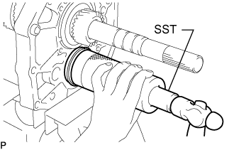
- SST
- 09316-60011
(09316-00011)
- HINT:
- Install the bearing while tapping the tip of the counter gear with a plastic-faced hammer so that the counter gear does not hit the side wall of the output shaft gear by being pushed forward.
Using a snap ring expander, install the snap ring.
| 6. INSTALL REVERSE IDLER GEAR SUB-ASSEMBLY |
Apply gear oil to each sliding part of the reverse idler gear sub-assembly and the reverse idler gear shaft, and install them to the intermediate plate.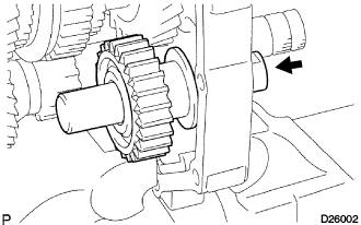
- NOTICE:
- Orient the groove side of the reverse idler shaft to the rear side and install it from the rear side.
| 7. INSTALL OUTPUT SHAFT REAR BEARING(MTM) RETAINER |
Install the output shaft rear bearing (MTM) retainer into the groove of the reverse idler gear shaft with the 4 bolts.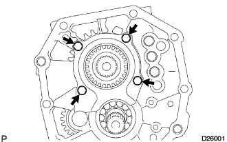
- Torque:
- 18 N*m{ 184 kgf*cm , 13 ft.*lbf }
| 8. INSTALL 5TH GEAR THRUST WASHER PIN |
Apply MP grease to the 5th gear thrust washer pin, and install it to the counter gear.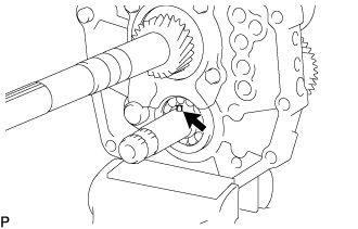
| 9. INSTALL 5TH GEAR THRUST WASHER |
Apply gear oil to the 5th gear thrust washer, and install it to the counter gear.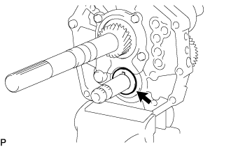
- NOTICE:
- Install the thrust washer so that its chamfer side faces to the front side.
| 10. INSTALL NO. 3 SYNCHROMESH SHIFTING KEY |
Apply gear oil to the sliding part of the No. 3 transmission hub sleeve, and install it to the counter shaft 5th gear.
- NOTICE:
- Be sure of the direction of the No. 3 transmission hub sleeve and the counter shaft 5th gear.
Install the 2 No. 3 synchromesh shifting keys and No. 3 synchromesh shifting key spring to the counter shaft 5th gear as shown in the illustration.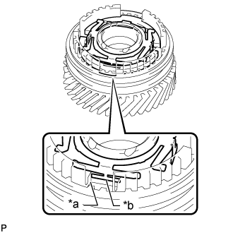
- HINT:
- When installing the No. 3 synchromesh shifting key spring, make sure the protrusion fits into the cutout.
Text in Illustration *a
Cutout
*b
Protrution
Using a snap ring expander, install the shaft snap ring to the counter shaft 5th gear.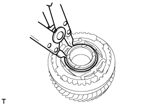
| 11. INSTALL COUNTER 5TH GEAR BEARING |
Apply gear oil to the counter 5th gear bearing and install it to the counter shaft 5th gear.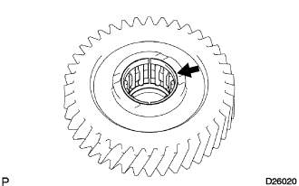
| 12. INSTALL COUNTER SHAFT 5TH GEAR |
Apply gear oil to the counter 5th gear and No. 3 transmission hub sleeve assembly, and install them to the counter gear.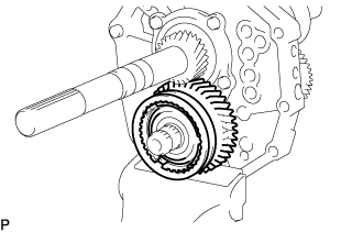
| 13. INSTALL OUTER NO.3 SYNCHRONIZER RING |
Apply gear oil to the outer No. 3 synchronizer ring, and install it to the counter gear.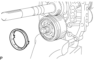
- NOTICE:
- Make sure that the No. 3 synchromesh shifting key fits into the grooves of the outer No. 3 synchronizer ring.
| 14. INSTALL No. 5 GEAR SPLINE PIECE |
Using SST and a press, install the No. 5 gear spline piece to the counter gear.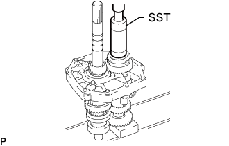
- SST
- 09316-60011
(09316-00011)
- NOTICE:
- Check that the gear rotates smoothly.
| 15. INSTALL COUNTER GEAR REAR SHAFT SNAP RING |
Select a counter gear rear shaft snap ring so that the thrust gap between the No. 5 gear spline piece and counter gear rear shaft snap ring is within the specified values. Use a brass bar and a hammer, install it to the counter gear.
- Standard clearance:
- 0.1 mm (0.0039 in.) or less
Mark
Thickness: mm (in.)
A
2.80 to 2.85 (0.1102 to 0.1122)
B
2.85 to 2.90 (0.1122 to 0.1141)
C
2.90 to 2.95 (0.1141 to 0.1160)
D
2.95 to 3.00 (0.1160 to 0.1181)
E
3.00 to 3.05 (0.1181 to 0.1200)
F
3.05 to 3.10 (0.1200 to 0.1220)
G
3.10 to 3.15 (0.1220 to 0.1240)
| 16. INSPECT COUNTER SHAFT 5TH GEAR THRUST CLEARANCE |
Using a feeler gauge, measure the counter shaft 5th gear thrust clearance.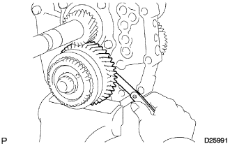
- Standard clearance:
- 0.10 to 0.35 mm (0.0039 to 0.0138 in.)
| 17. INSPECT COUNTER SHAFT 5TH GEAR RADIAL CLEARANCE |
Using a dial indicator, measure the radial clearance of the counter shaft 5th gear.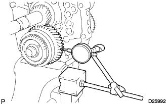
- Standard clearance:
- 0.015 to 0.068 mm (0.0059 to 0.0027 in.)
| 18. INSTALL OUTPUT SHAFT REAR BEARING |
Using SST and a press, install a new output shaft rear bearing and output shaft spacer to the output shaft.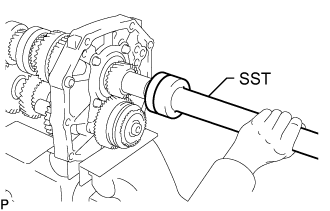
- SST
- 09309-35010
| 19. INSTALL OUTPUT SHAFT BEARING SHAFT SNAP RING |
Select an output shaft bearing shaft snap ring so that the thrust gap between the snap ring and the bearing is within the specified values. Use a brass bar and a hammer to install it to the output shaft assembly.
- Standard clearance:
- 0.1 mm (0.0039 in.) or less
Mark
Thickness: mm (in.)
A
2.65 to 2.70 (0.1043 to 0.1063)
B
2.70 to 2.75 (0.1063 to 0.1083)
C
2.75 to 2.80 (0.1083 to 0.1102)
D
2.80 to 2.85 (0.1102 to 0.1122)
E
2.85 to 2.90 (0.1122 to 0.1141)
F
2.90 to 2.95 (0.1141 to 0.1160)
G
2.95 to 3.00 (0.1160 to 0.1181)
H
3.00 to 3.05 (0.1181 to 0.1200)
J
3.05 to 3.10 (0.1200 to 0.1220)
K
3.10 to 3.15 (0.1220 to 0.1240)
L
3.15 to 3.20 (0.1240 to 0.1260)
M
3.20 to 3.25 (0.1260 to 0.1280)
N
3.25 to 3.30 (0.1280 to 0.1299)
P
3.30 to 3.35 (0.1299 to 0.1319)
Q
3.35 to 3.40 (0.1319 to 0.1339)
R
3.40 to 3.45 (0.1339 to 0.1358)
S
3.45 to 3.50 (0.1358 to 0.1378)
| 20. INSTALL SPEEDOMETER DRIVE (MTM) GEAR |
Using snap ring expander, install the snap ring.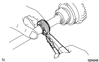
Install the steel ball and speedometer drive (MTM) gear.
Using snap ring expander, install the snap ring.
| 21. INSTALL REVERSE SHIFT ARM BRACKET |
Install the reverse shift arm to the reverse shift arm bracket with a new snap ring.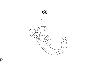
Insert the tip of the reverse shift arm into the reverse idler gear.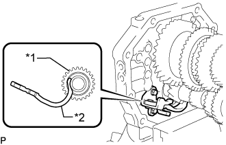
Text in Illustration *1
Reverse Idler Gear
*2
Reverse Shift Arm
Install the reverse shift arm bracket with the 2 bolts.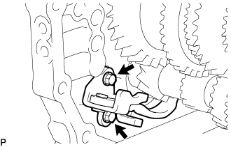
- Torque:
- 18 N*m{ 184 kgf*cm , 13 ft.*lbf }
Install the torsion spring to the reverse shift arm bracket.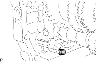
- NOTICE:
- Make sure that the torsion spring is securely installed to the reverse shift arm.
| 22. INSTALL REVERSE SHIFT FORK |
Install the reverse shift fork to the reverse shift arm.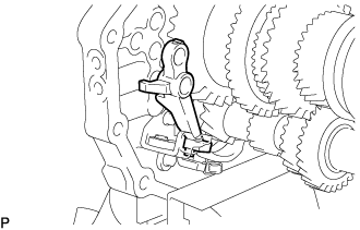
| 23. INSTALL REVERSE SHIFT FORK SHAFT |
Install the No. 3 gear shift fork to the No. 3 transmission hub sleeve and the reverse shift fork shaft to the intermediate plate from the front side.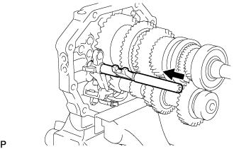
Install the straight pin to the reverse shift fork.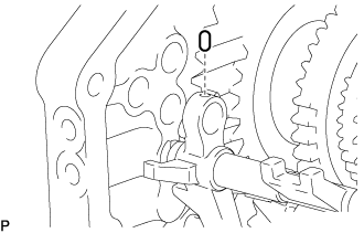
Using a brass bar and a hammer, install the snap ring to the reverse shift fork shaft.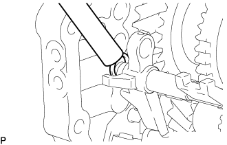
Using a 5 mm pin punch and a hammer, install the slotted spring pin into the No. 3 gear shift fork.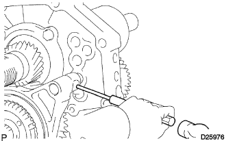
| 24. INSTALL NO. 2 GEAR SHIFT FORK SHAFT |
Install the No. 1 shift interlock roller to the intermediate plate.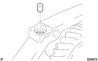
Install the No. 1 gear shift fork to the reverse gear.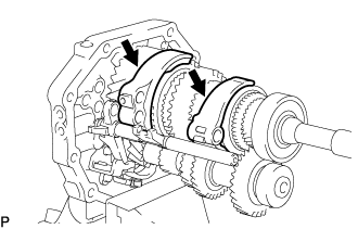
Install the No. 2 gear shift fork to the No. 2 transmission hub sleeve.
Install the No. 2 gear shift head and No. 2 gear shift fork shaft to the intermediate plate from the front side.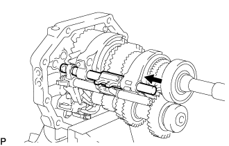
Using a 5 mm pin punch and a hammer, install the slotted spring pin into the No. 2 gear shift fork shaft.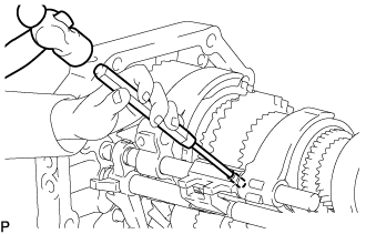
Install a new bolt to the No. 2 gear shift fork.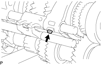
- Torque:
- 20 N*m{ 199 kgf*cm , 14 ft.*lbf }
Using a brass bar and a hammer, install the snap ring to the No. 2 gear shift fork shaft.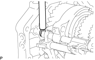
| 25. INSTALL SHIFT FORK SHAFT STOPPER |
Install the shift fork shaft stopper to the No. 2 gear shift fork shaft.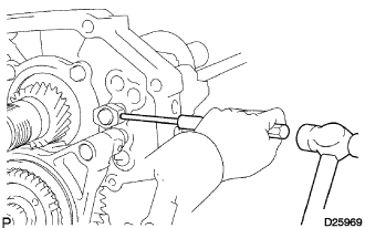
Using a 5 mm pin punch and a hammer, install the slotted spring pin into the No. 2 gear shift fork shaft.
| 26. INSTALL NO. 1 GEAR SHIFT FORK SHAFT |
Install the shift interlock pin and No. 1 shift interlock roller into the intermediate plate.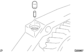
Apply gear oil to the No. 1 gear shift fork shaft, and install it to the intermediate plate from the front side.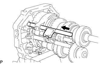
Install a new bolt to the No. 1 gear shift fork.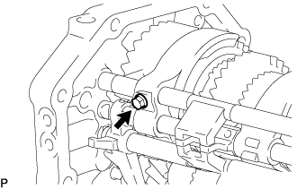
- Torque:
- 20 N*m{ 199 kgf*cm , 14 ft.*lbf }
Using a brass bar and a hammer, install the snap ring to the No. 1 gear shift fork shaft.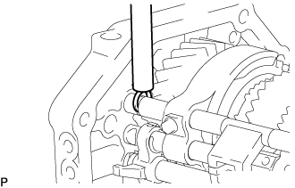
| 27. INSTALL SHIFT FORK SHAFT STOPPER |
Install the shift fork shaft stopper to the No. 1 gear shift fork shaft.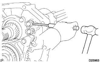
Using a 5 mm pin punch and a hammer, install the slotted spring pin into the No. 2 gear shift fork shaft.
| 28. INSTALL NO. 1 SHIFT DETENT BALL SPRING SEAT |
Install the 2 compression springs and 2 shift detent balls into the intermediate plate.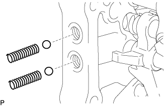
Using a T40 "TORX" socket wrench, install the 2 No. 1 shift detent ball spring seats to the intermediate plate.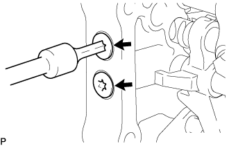
- Torque:
- 19 N*m{ 189 kgf*cm , 14 ft.*lbf }
Install the shift detent ball and compression spring into the intermediate plate.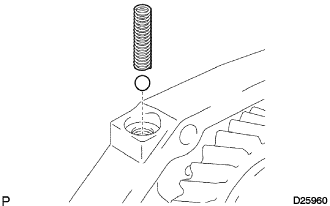
Using a T40 "TORX" socket wrench, install the No. 1 shift detent ball spring seat to the intermediate plate.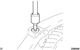
- Torque:
- 19 N*m{ 189 kgf*cm , 14 ft.*lbf }
| 29. INSTALL TRANSMISSION MAGNET |
Clean the transmission magnet, and install it to the intermediate plate.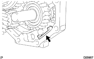
| 30. INSTALL MANUAL TRANSMISSION CASE |
Apply seal packing to the manual transmission case as shown in the illustration.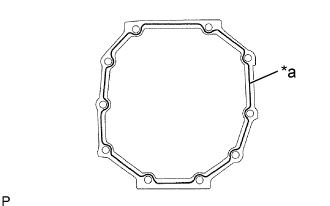
- Seal packing:
- Toyota Genuine Seal Packing 1281, Three Bond 1281 or equivalent
- Seal diameter :
- 1.2 mm (0.0472 in.)
Text in Illustration *a
Seal Packing
- NOTICE:
- Assemble parts within 10 minutes of application. Otherwise, the packing (FIPG) material must be removed and reapplied.
Using a plastic-faced hammer, tap the manual transmission case to attach it to the intermediate plate.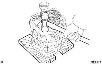
| 31. INSTALL NO. 1 COUNTER GEAR FRONT BEARING SNAP RING |
Using a snap ring expander, install the No. 1 counter gear front bearing snap ring to the manual transmission case.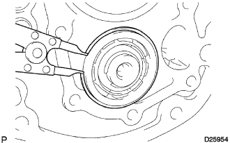
| 32. INSTALL FRONT BEARING SHAFT SNAP RING |
Using a snap ring expander, install the front bearing shaft snap ring to the manual transmission case.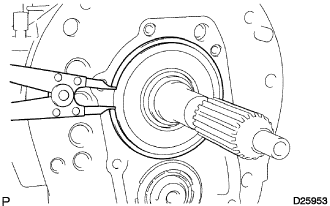
| 33. INSTALL FRONT TRANSMISSION BEARING RETAINER OIL SEAL |
Using SST and a hammer, install a new front transmission bearing retainer oil seal to the front bearing retainer.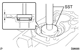
- SST
- 09950-60010
(09951-00300, 09951-00520, 09952-06010, 09951-07100)
- Drive in depth:
- 11.2 to 12.2 mm (0.4409 to 0.4803 in.)
Coat the lip of the transmission front bearing retainer oil seal with MP grease.
| 34. INSTALL FRONT BEARING RETAINER (MTM) |
Apply seal packing to the front bearing retainer (MTM) as shown in the illustration.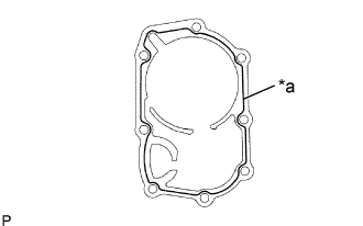
- Seal packing:
- Toyota Genuine Seal Packing 1281, Three Bond 1281 or equivalent
- Seal diameter :
- 1.2 mm (0.0472 in.)
Text in Illustration *a
Seal Packing
- NOTICE:
- Assemble parts within 10 minutes of application. Otherwise, the packing (FIPG) material must be removed and reapplied.
Apply seal packing to the bolts.
- Seal packing:
- Toyota Genuine Seal Packing 1281, Three Bond 1281 or equivalent
Install the front bearing retainer (MTM) to the manual transmission case with the 8 bolts.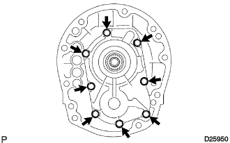
- Torque:
- 17 N*m{ 168 kgf*cm , 12 ft.*lbf }
| 35. INSTALL MANUAL TRANSMISSION EXTENSION HOUSING OIL SEAL |
Using SST and a hammer, install a new manual transmission extension housing oil seal to the extension housing sub-assembly.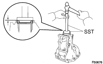
- SST
- 09710-30050
09950-70010 (09951-07100)
- Drive in depth:
- -0.5 to 0.5 mm (-0.020 to 0.020 in.)
- NOTICE:
- Be careful not to damage the oil seal lip.
Lightly apply MP grease to the tip of the manual transmission extension housing oil seal.
| 36. INSTALL EXTENSION HOUSING OIL RECEIVER PIPE |
Install the extension housing oil receiver pipe with the bolt.
- Torque:
- 11 N*m{ 112 kgf*cm , 8 ft.*lbf }
| 37. INSTALL No. 1 EXTENSION HOUSING OIL RECEIVER PIPE |
Install the No. 1 extension housing oil receiver pipe to the extension (MTM) housing sub-assembly.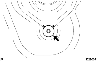
| 38. INSTALL EXTENSION (MTM) HOUSING SUB-ASSEMBLY |
Apply seal packing to the extension (MTM) housing sub-assembly as shown in the illustration.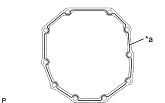
- Seal packing:
- Toyota Genuine Seal Packing 1281, Three Bond 1281 or equivalent
- Seal diameter :
- 1.2 mm (0.0472 in.)
Text in Illustration *a
Seal Packing
- NOTICE:
- Assemble parts within 10 minutes of application. Otherwise, the packing (FIPG) material must be removed and reapplied.
Install the extension (MTM) housing sub-assembly to the manual transmission case with the 10 bolts.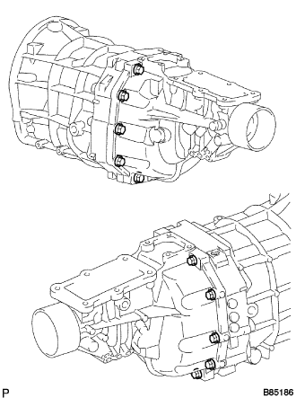
- Torque:
- 37 N*m{ 377 kgf*cm , 27 ft.*lbf }
| 39. INSTALL SHIFT LEVER SHAFT HOUSING SUB-ASSEMBLY |
Apply seal packing to the shift lever shaft housing sub-assembly as shown in the illustration.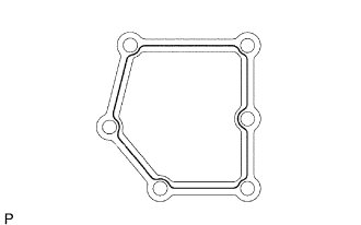
- Seal packing:
- Toyota Genuine Seal Packing 1281, Three Bond 1281 or equivalent
Install the shift lever shaft housing sub-assembly to the manual transmission case with the 6 bolts.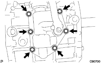
- Torque:
- 17 N*m{ 168 kgf*cm , 12 ft.*lbf }
| 40. INSTALL EXTENSION HOUSING DUST(MTM) DEFLECTOR |
Using a plastic-faced hammer, install the extension housing dust (MTM) deflector to the extension (MTM) housing sub-assembly.
| 41. INSTALL EXTENSION HOUSING(MTM) COVER |
Install the extension housing (MTM) cover and a new gasket to the extension (MTM) housing sub-assembly with the 6 bolts.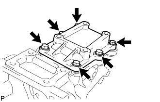
- Torque:
- 18 N*m{ 183 kgf*cm , 13 ft.*lbf }
| 42. INSTALL SPEEDOMETER SENSOR |
Install a new O-ring to the speedometer sensor.
Install the speedometer sensor with the bolt.
- Torque:
- 11 N*m{ 112 kgf*cm , 8 ft.*lbf }
| 43. INSTALL BACK UP LIGHT SWITCH ASSEMBLY |
Using SST, install the back up light switch assembly and a new gasket to the manual transmission case.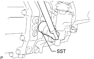
- SST
- 09817-16011
- Torque:
- 44 N*m{ 448 kgf*cm , 32 ft.*lbf }
| 44. INSTALL CLUTCH HOUSING |
Install the clutch housing to the manual transmission case with the 9 bolts.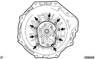
- Torque:
- 36 N*m{ 367 kgf*cm , 27 ft.*lbf }
| 45. INSTALL MANUAL TRANSMISSION DRAIN PLUG |
Install the manual transmission drain plug to the manual transmission case through a new gasket.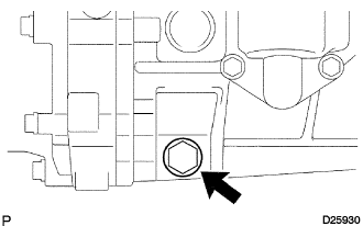
- Torque:
- 37 N*m{ 377 kgf*cm , 27 ft.*lbf }
| 46. INSTALL MANUAL TRANSMISSION FILLER PLUG |
Install the manual transmission filler plug to the manual transmission case through a new gasket.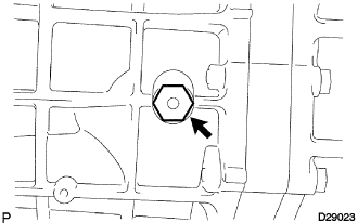
- Torque:
- 37 N*m{ 377 kgf*cm , 27 ft.*lbf }