INSTALLATION
Removal / installation · Vehicles built from Jan 2017
- NOTICE:
- When replacing the parts in the following chart (A), replace the No. 1 injection pipe sub-assembly, No. 2 injection pipe sub-assembly and/or fuel inlet pipe sub-assembly with new ones.
Replaced Parts (A)
Pipes Requiring New Replacement
Injector assembly (including shuffling the injector assemblies between the cylinders)
- No. 1 injection pipe sub-assembly
- No. 2 injection pipe sub-assembly
Supply pump assembly
Fuel inlet pipe sub-assembly
- Common rail assembly
- Cylinder block sub-assembly
- Cylinder head sub-assembly
- Cylinder head gasket
- Timing chain case assembly
- No. 1 injection pipe sub-assembly
- No. 2 injection pipe sub-assembly
- Fuel inlet pipe sub-assembly
- No. 1 injection pipe sub-assembly
- After removing the No. 1 injection pipe sub-assembly, No. 2 injection pipe sub-assembly and/or fuel inlet pipe sub-assembly, clean them with a brush and compressed air.
- The injector assembly is a precision instrument. Do not use the injector assembly if it is struck or dropped.
- The supply pump assembly is a precision instrument. Do not use the supply pump assembly if it is struck or dropped.
- Hold the supply pump assembly itself during removal and installation. Do not hold the pre-stroke control valve or fuel pipe, etc.
- Make sure foreign matter does not enter the fuel path.
- When replacing the parts in the following chart (A), replace the No. 1 injection pipe sub-assembly, No. 2 injection pipe sub-assembly and/or fuel inlet pipe sub-assembly with new ones.
| 1. INSTALL CAMSHAFT |

Check that the valve rocker arm sub-assembly is firmly set to the valve lash adjuster assembly.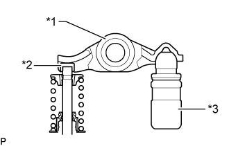

Text in Illustration *1
Valve Rocker Arm Sub-assembly
*2
Valve Stem Cap
*3
Valve Lash Adjuster Assembly
Apply a light coat of engine oil to the camshaft journals of the cylinder head sub-assembly and the thrust portion of the camshaft.
Align the paint mark of the No. 2 chain sub-assembly and timing mark of the camshaft timing sprocket, and install the camshaft timing sprocket to the No. 2 chain sub-assembly.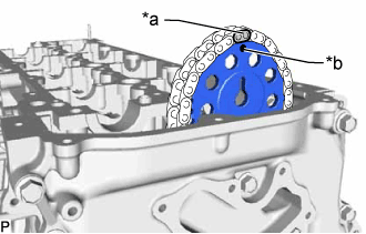
Text in Illustration *a
Paint Mark
*b
Timing Mark
- HINT:
- Make sure the timing mark of the camshaft timing sprocket face the front side.
Align the knock pin of the No. 1 camshaft to the groove of the sprocket and install the No. 1 camshaft to the camshaft timing sprocket, and set the bolt.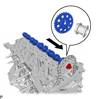
Align the paint mark of the No. 2 chain sub-assembly and timing mark of the camshaft timing sprocket, and install the camshaft timing sprocket to the No. 2 chain sub-assembly.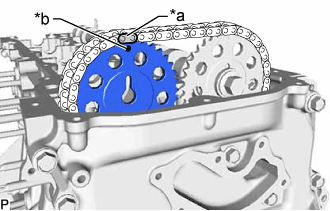
Text in Illustration *a
Paint Mark
*b
Timing Mark
- HINT:
- Make sure the timing mark of the camshaft timing sprocket face the front side.
Align the knock pin of the No. 2 camshaft to the groove of the sprocket and install the No. 2 camshaft to the camshaft timing sprocket, and set the bolt.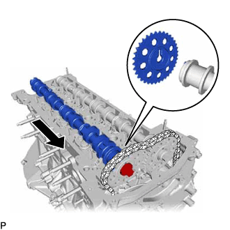
- HINT:
-
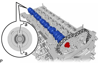
- Groove is at the rear end of the No. 2 camshaft.
Text in Illustration *a
Groove
Check the timing mark of the camshaft timing sprocket and the paint mark of the No. 2 chain sub-assembly.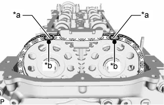
Text in Illustration *a
Paint Mark
*b
Timing Mark
Set the No. 1 camshaft bearing cap and 8 No. 2 camshaft bearing caps to the cylinder head sub-assembly as shown in the illustration.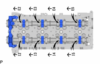
Temporarily install the 20 bolts.
Uniformly tighten the 20 bolts in several steps in the order shown in the illustration.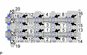
- Torque:
- for bolt A:
- 10 N*m{ 102 kgf*cm , 7 ft.*lbf }
- for bolt B:
- 21 N*m{ 214 kgf*cm , 15 ft.*lbf }
Text in Illustration 
Bolt A

Bolt B
Hold the hexagonal portion of the No. 1 camshaft and No. 2 camshaft with a wrench, and tighten the 2 bolts.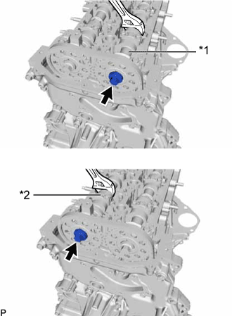
- Torque:
- 81 N*m{ 826 kgf*cm , 60 ft.*lbf }
Text in Illustration *1
No. 1 Camshaft
*2
No. 2 Camshaft
- NOTICE:
- Be careful not to damage the cylinder head sub-assembly with the wrench.
Remove the pin from the No. 2 chain tensioner assembly.
Install a new gasket and the oil pump relief valve plug to the timing chain cover.
- Torque:
- 46 N*m{ 469 kgf*cm , 34 ft.*lbf }
Clean and degrease the contact surfaces of the cylinder head sub-assembly and No. 3 camshaft bearing cap.
Apply seal packing to the specified areas as shown in the illustration.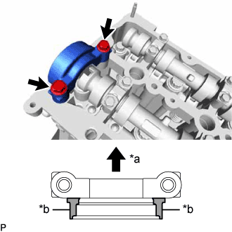
- Seal packing:
- Toyota Genuine Seal Packing Black, Three Bond 1207B or equivalent
- Standard seal diameter:
- 3.0 mm (0.118 in.)
Text in Illustration *a
Engine Front
*b
Seal Packing
- NOTICE:
- Do not allow seal packing to contact the oil passage of the No. 3 camshaft bearing cap.
- After applying seal packing, install the No. 3 camshaft bearing cap within 3 minutes and tighten the bolts within 10 minutes.
- Do not start the engine for at least 2 hours after installation.
- Do not allow seal packing to contact the oil passage of the No. 3 camshaft bearing cap.
Install the No. 3 camshaft bearing cap with the 2 bolts.
- Torque:
- 21 N*m{ 214 kgf*cm , 15 ft.*lbf }
Wipe off excess seal packing from between No. 3 camshaft bearing cap and cylinder head sub-assembly.
| 2. INSTALL TIMING CHAIN GUIDE |
Install the timing chain guide to the cylinder head sub-assembly with the bolt.
- Torque:
- 10 N*m{ 102 kgf*cm , 7 ft.*lbf }
| 3. INSTALL CYLINDER HEAD COVER SUB-ASSEMBLY |
Apply a light coat of engine oil to the O-ring of the camshaft position sensor.
Install a new cylinder head cover gasket, No. 2 cylinder head cover gasket and 2 camshaft bearing cap oil hole gaskets to the cylinder head cover sub-assembly.
Clean and degrease the contact surfaces of the cylinder head cover sub-assembly and cylinder head sub-assembly.
Apply seal packing as shown in the illustration.
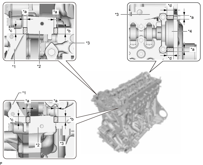
Text in Illustration *1
Timing Chain Cover Sub-assembly
*2
Timing Chain Case Assembly
*3
Cylinder Head Sub-assembly
*4
No. 3 Camshaft Bearing Cap
*a
Seal Diameter: 3.0 to 6.0 mm (0.118 to 0.236 in.)
*b
Application Width: 7.0 mm (0.276 in.)
*c
Application Width: 9.0 mm (0.354 in.)
*d
Application Width: 11.0 mm (0.433 in.)
- Seal packing:
- Toyota Genuine Seal Packing Black, Three Bond 1207B or equivalent
- Standard seal diameter:
- 3.0 to 6.0 mm (0.118 to 0.236 in.)
- NOTICE:
- Remove any oil from the contact surface.
- Install the cylinder head cover sub-assembly within 3 minutes and tighten the bolts within 10 minutes after applying seal packing.
- Do not add engine oil for at least 2 hours after installation.
- Do not start the engine within 2 hours after installation.
- Remove any oil from the contact surface.
Tighten the 14 bolts, 4 nozzle holder clamp seats, 2 nuts and camshaft position sensor in the order shown in the illustration.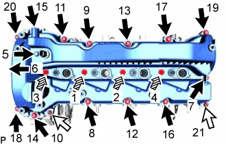
- Torque:
- 10 N*m{ 107 kgf*cm , 7 ft.*lbf }
- NOTICE:
- When reusing the camshaft position sensor, check the O-rings.
- Make sure that the O-ring is not cracked or jammed when installing it on the cylinder head cover sub-assembly.
- Replace with a new part if it is dropped or if it receives a strong impact.
- Check the torque of bolts 1 to 4 again.
- When reusing the camshaft position sensor, check the O-rings.
Text in Illustration
Bolt
Nut

Nozzle Holder Clamp Seat
| 4. INSTALL CAMSHAFT OIL SEAL RETAINER |
- NOTICE:
- If the camshaft oil seal retainer is dropped, replace it with a new one.
Before installing a new camshaft oil seal retainer, clean the installation surface of the No. 3 camshaft bearing cap and cylinder head sub-assembly and remove any foreign matter.
Using SST and a hammer, tap in a new camshaft oil seal retainer to the No. 3 camshaft bearing cap and cylinder head sub-assembly as shown in the illustration.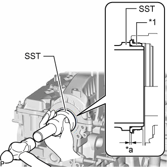
- SST
- 09223-22010
- Standard depth:
- -0.5 to 0.8 mm (-0.0197 to 0.0315 in.)
Text in Illustration *1
Camshaft Oil Seal Retainer
*a
Depth
| 5. INSTALL VACUUM PUMP ASSEMBLY |
Coat 2 new O-rings with engine oil, and install them to the vacuum pump assembly.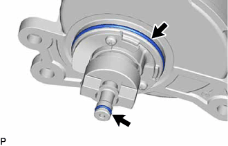
Install the vacuum pump assembly so that the coupling teeth of the vacuum pump assembly labeled A and the groove of the No. 2 camshaft labeled B can engage.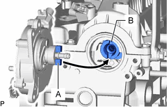
Install the vacuum pump assembly to the cylinder head sub-assembly with the 3 bolts.
- Torque:
- 21 N*m{ 214 kgf*cm , 15 ft.*lbf }
Connect the No. 1 vacuum transmitting hose sub-assembly to the vacuum pump assembly.
| 6. CONNECT BRACKET |
Connect the bracket to the cylinder head sub-assembly with the 2 bolts.
- Torque:
- 10 N*m{ 102 kgf*cm , 7 ft.*lbf }
Attach the 3 clamp and connect the 2 connectors to the bracket.
| 7. INSTALL NOZZLE HOLDER GASKET |
Install 4 new nozzle holder gaskets to the cylinder head cover sub-assembly.
| 8. TEMPORARILY INSTALL INJECTOR ASSEMBLY |
- HINT:
- Before installing the injector assembly, check for carbon, foreign matter, etc. on the seal surfaces of the cylinder head sub-assembly and injector assembly. If there is foreign matter, remove it before installing the injector assembly.
Install 4 new injection nozzle seats to the cylinder head sub-assembly.
Apply a light coat of engine oil to the O-ring on each injector assembly.
Install a new O-ring to each injector assembly.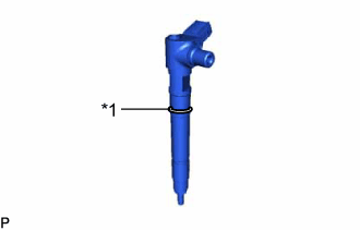
Text in Illustration *1
O-Ring
Install the 4 injector assemblies to the cylinder head sub-assembly.
- NOTICE:
- Fit the injector assembly to the injection nozzle seats.
Install the nozzle holder clamps and washers as shown in the illustration.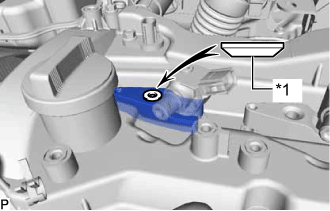
Text in Illustration *1
Washer
- NOTICE:
- Pay attention to the mounting orientation (beveled edge) of the washer.
Temporarily install the nozzle holder clamp bolts.
- NOTICE:
- When temporarily installing the nozzle holder clamp bolt to the No. 1 nozzle holder clamp, make sure that the bolt and clamp are not at an angle.
- HINT:
- Apply a light coat of engine oil to the threads of the nozzle holder clamp bolts.
| 9. TEMPORARILY INSTALL NO. 1 INJECTION PIPE SUB-ASSEMBLY AND NO. 2 INJECTION PIPE SUB-ASSEMBLY |
Temporarily install the 2 No. 2 injection pipe sub-assemblies with the 4 union nuts.
Temporarily install the 2 No. 1 injection pipe sub-assemblies with the 4 union nuts.
| 10. TIGHTEN INJECTOR ASSEMBLY |
Tighten the 4 nozzle holder clamp bolts.
- Torque:
- 21 N*m{ 214 kgf*cm , 15 ft.*lbf }
| 11. TIGHTEN NO. 1 INJECTION PIPE SUB-ASSEMBLY AND NO. 2 INJECTION PIPE SUB-ASSEMBLY |
Using SST, tighten the 8 union nuts of the No. 1 and No. 2 injection pipe sub-assemblies.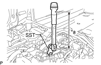
Text in Illustration *a
Torque Wrench Fulcrum Length
- Torque:
- Specified tightening torque:
- 40 N*m{ 408 kgf*cm , 30 ft.*lbf }
- HINT:
- Calculate the torque wrench reading when changing the fulcrum length of the torque wrench.
- When using SST (fulcrum length of 50 mm (1.97 in.)) + torque wrench (fulcrum length of 180 mm (7.09 in.)): 31 N*m (316 kgf*cm, 23 ft.*lbf)
- Calculate the torque wrench reading when changing the fulcrum length of the torque wrench.
| 12. INSTALL NOZZLE LEAKAGE PIPE ASSEMBLY |
Temporarily install the nozzle leakage pipe assembly and 4 new gaskets with the 4 union bolts and bolt.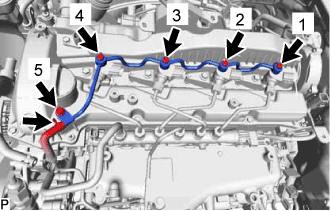
Tighten the 4 union bolts and bolt in the order shown in the illustration.
- Torque:
- for union bolt:
- 12 N*m{ 122 kgf*cm , 9 ft.*lbf }
- Torque:
- for bolt:
- 10 N*m{ 102 kgf*cm , 7 ft.*lbf }
Connect the No. 5 fuel hose to the nozzle leakage pipe assembly.
| 13. INSTALL NO. 1 FUEL PIPE |
Connect the No. 1 fuel pipe to the No. 4 fuel pipe.
Install a new gasket and the No. 1 fuel pipe to the cylinder head cover sub-assembly and No. 1 injector holder with the union bolt and bolt.
- Torque:
- for bolt:
- 10 N*m{ 102 kgf*cm , 7 ft.*lbf }
- for union bolt:
- 26 N*m{ 265 kgf*cm , 19 ft.*lbf }
| 14. INSTALL HARNESS BRACKET |
Install the harness bracket with the bolt.
- Torque:
- 10 N*m{ 102 kgf*cm , 7 ft.*lbf }
| 15. INSTALL WIRING HARNESS CLAMP BRACKET |
Install the wiring harness clamp bracket the cylinder head cover sub-assembly with the bolt.
- Torque:
- 10 N*m{ 102 kgf*cm , 7 ft.*lbf }
Connect the pressure discharge valve connector to the common rail assembly.
| 16. INSTALL INSTALL NO. 1 EGR COOLER AND NO. 2 EGR VALVE ASSEMBLY WITH ELECTRIC EGR CONTROL VALVE ASSEMBLY |
Temporarily install the No. 1 EGR cooler and No. 2 EGR valve assembly with electric EGR control valve assembly to the intake manifold with the 4 bolts.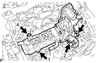
Tighten the 4 bolts in the order shown in the illustration.
- HINT:
- Make sure to tighten the bolts in the order.
- Torque:
- 21 N*m{ 214 kgf*cm , 15 ft.*lbf }
| 17. INSTALL VACUUM CONTROL VALVE SET |
Install the vacuum control valve set to the intake manifold with the 2 bolts.
- Torque:
- 10 N*m{ 102 kgf*cm , 7 ft.*lbf }
Connect the 2 vacuum hoses to the vacuum control valve set and No. 2 EGR valve assembly.
Connect the connector to the vacuum control valve set.
| 18. INSTALL NO. 1 EGR PIPE SUB-ASSEMBLY |
Using an E8 "TORX" socket wrench, install 2 new stud bolts to the exhaust manifold.
- Torque:
- 10 N*m{ 102 kgf*cm , 7 ft.*lbf }
Install 2 new gaskets and the No. 1 EGR pipe sub-assembly to the exhaust manifold and EGR valve adapter with 4 new nuts.
- Torque:
- 29 N*m{ 296 kgf*cm , 21 ft.*lbf }
Connect the No. 1 EGR pipe sub-assembly to the vacuum transmitting pipe sub-assembly with the bolt.
- Torque:
- 10 N*m{ 102 kgf*cm , 7 ft.*lbf }
| 19. INSTALL NO. 2 EGR PIPE |
Install 2 new gaskets and No. 2 EGR pipe to the electric EGR control valve assembly and the intake manifold with the 4 nuts.
- Torque:
- 29 N*m{ 296 kgf*cm , 21 ft.*lbf }
| 20. CONNECT NO. 4 WATER BY-PASS PIPE SUB-ASSEMBLY |
Connect the No. 4 water by-pass pipe sub-assembly to the intake manifold with the 2 bolts.
- Torque:
- 10 N*m{ 102 kgf*cm , 7 ft.*lbf }
Connect the water hose to the No. 2 EGR valve assembly, and slide the clamp to secure the hose.
Connect the No. 7 water by-pass hose to the No. 1 EGR cooler, and slide the clamp to secure the hose.
| 21. INSTALL NO. 3 WATER BY-PASS PIPE SUB-ASSEMBLY |
Install the No. 3 water by-pass pipe sub-assembly to the No. 1 EGR cooler with the 2 bolts.
- Torque:
- 10 N*m{ 102 kgf*cm , 7 ft.*lbf }
Connect the No. 9 water by-pass hose to the electric EGR control valve assembly, and slide the clamp to secure the hose.
Connect the No. 8 water by-pass hose to the No. 3 water by-pass pipe sub-assembly, and slide the clamp to secure the hose.
Connect the No. 4 fuel hose to the No. 3 water by-pass pipe sub-assembly.
| 22. INSTALL EGR VALVE BRACKET |
Install the EGR valve bracket to the electric EGR control valve assembly and intake manifold with the bolt and nut.
- Torque:
- 21 N*m{ 214 kgf*cm , 15 ft.*lbf }
| 23. INSTALL DIESEL THROTTLE BODY ASSEMBLY |
Connect the connector to install the emission control valve wire to the diesel throttle body assembly.
Install a new gasket and the diesel throttle body assembly with the 2 bolts and 2 nuts.
- Torque:
- 10 N*m{ 102 kgf*cm , 7 ft.*lbf }
Connect the connector and clamp.
| 24. INSTALL GAS FILTER BRACKET |
Install the gas filter bracket to the diesel throttle body assembly with the bolt.
- Torque:
- 10 N*m{ 102 kgf*cm , 7 ft.*lbf }
| 25. INSTALL GAS FILTER |
Install the gas filter to the gas filter bracket.
Connect the 2 vacuum hoses to the turbo pressure sensor and intake manifold.
| 26. INSTALL TURBO PRESSURE SENSOR |
Install the diesel turbo pressure sensor to the No. 3 water by-pass pipe sub-assembly with the bolt.
- Torque:
- 10 N*m{ 102 kgf*cm , 7 ft.*lbf }
Connect the connector to the diesel turbo pressure sensor.
| 27. INSTALL NO. 2 WATER BY-PASS PIPE |
Connect the heater hose to the No. 2 water by-pass pipe.
Install the No. 2 water by-pass pipe with the 2 bolts.
- Torque:
- 10 N*m{ 102 kgf*cm , 7 ft.*lbf }
| 28. INSTALL NO. 16 WATER BY-PASS HOSE |
Install the No. 16 water by-pass hose to the No. 1 EGR cooler and No. 2 water by-pass pipe, and slide the 2 clamps to secure the hoses.
| 29. INSTALL VACUUM TUBE CONNECTOR HOSE |
Install the vacuum tube connector hose to the cylinder head sub-assembly and intake manifold with the 2 bolts.
- Torque:
- 10 N*m{ 102 kgf*cm , 7 ft.*lbf }
Connect the vacuum tube connector hose to the vacuum pump assembly, and slide the clamp to secure the hose.
| 30. INSTALL ENGINE ASSEMBLY |