REMOVAL
Removal / installation · Vehicles built from Jan 2017
- NOTICE:
- When replacing the parts in the following chart (A), replace the No. 1 injection pipe sub-assembly, No. 2 injection pipe sub-assembly and/or fuel inlet pipe sub-assembly with new ones.
Replaced Parts (A)
Pipes Requiring New Replacement
Injector assembly (including shuffling the injector assemblies between the cylinders)
- No. 1 injection pipe sub-assembly
- No. 2 injection pipe sub-assembly
Supply pump assembly
Fuel inlet pipe sub-assembly
- Common rail assembly
- Cylinder block sub-assembly
- Cylinder head sub-assembly
- Cylinder head gasket
- Timing chain case assembly
- No. 1 injection pipe sub-assembly
- No. 2 injection pipe sub-assembly
- Fuel inlet pipe sub-assembly
- No. 1 injection pipe sub-assembly
- After removing the No. 1 injection pipe sub-assembly, No. 2 injection pipe sub-assembly and/or fuel inlet pipe sub-assembly, clean them with a brush and compressed air.
- The injector assembly is a precision instrument. Do not use the injector assembly if it is struck or dropped.
- The supply pump assembly is a precision instrument. Do not use the supply pump assembly if it is struck or dropped.
- Hold the supply pump assembly itself during removal and installation. Do not hold the pre-stroke control valve or fuel pipe, etc.
- Make sure foreign matter does not enter the fuel path.
- When replacing the parts in the following chart (A), replace the No. 1 injection pipe sub-assembly, No. 2 injection pipe sub-assembly and/or fuel inlet pipe sub-assembly with new ones.
| 1. REMOVE ENGINE ASSEMBLY |

| 2. REMOVE VACUUM TUBE CONNECTOR HOSE |
Slide the clamp and disconnect the vacuum tube connector hose from the vacuum pump assembly.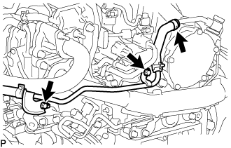

Remove the 2 bolts and vacuum tube connector hose from the cylinder head sub-assembly and intake manifold.
| 3. REMOVE NO. 16 WATER BY-PASS HOSE |
Slide the 2 clamps and remove the No. 16 water by-pass hose from the No. 1 EGR cooler and No. 2 water by-pass pipe.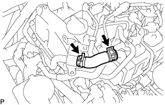
| 4. REMOVE NO. 2 WATER BY-PASS PIPE |
Disconnect the heater hose from the No. 2 water by-pass pipe.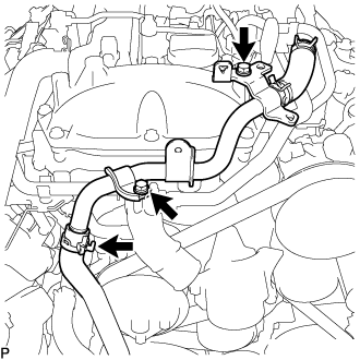
Remove the 2 bolts and No. 2 water by-pass pipe.
| 5. REMOVE TURBO PRESSURE SENSOR |
Disconnect the connector from the diesel turbo pressure sensor.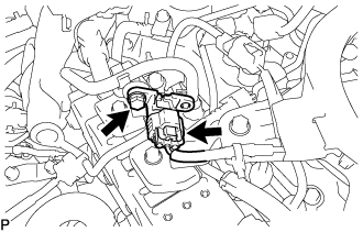
Remove the bolt and diesel turbo pressure sensor from the No. 3 water by-pass pipe sub-assembly.
| 6. REMOVE GAS FILTER |
Disconnect the 2 vacuum hoses from the turbo pressure sensor and intake manifold.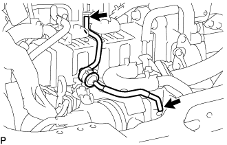
Remove the gas filter from the gas filter bracket.
| 7. REMOVE GAS FILTER BRACKET |
Remove the bolt and gas filter bracket from the diesel throttle body assembly.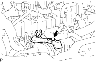
| 8. REMOVE DIESEL THROTTLE BODY ASSEMBLY |
Disconnect the connector and clamp.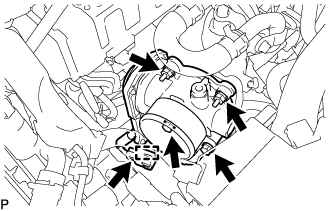
Remove the 2 bolts, 2 nuts, diesel throttle body and gasket.
Disconnect the connector to remove the emission control valve wire from the diesel throttle body assembly.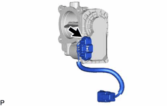
| 9. REMOVE NO. 3 WATER BY-PASS PIPE SUB-ASSEMBLY |
Disconnect the No. 4 fuel hose from the No. 3 water by-pass pipe sub-assembly.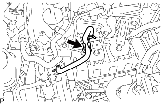
Slide the clamp and disconnect the No. 8 water by-pass hose from the No. 3 water by-pass pipe sub-assembly.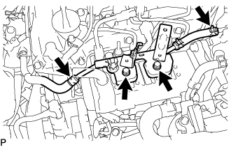
Slide the clamp and disconnect the No. 9 water by-pass hose from the electric EGR control valve assembly.
Remove the 2 bolts and No. 3 water by-pass pipe sub-assembly from the No. 1 EGR cooler.
| 10. DISCONNECT NO. 4 WATER BY-PASS PIPE SUB-ASSEMBLY |
Slide the clamp and disconnect the No. 7 water by-pass hose from the No. 1 EGR cooler.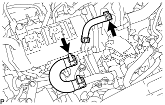
Slide the clamp and disconnect the water hose from the No. 2 EGR valve assembly.
Remove the 2 bolts and disconnect the No. 4 water by-pass pipe sub-assembly from the intake manifold.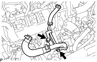
| 11. REMOVE EGR VALVE BRACKET |
Remove the bolt, nut and EGR valve bracket from the electric EGR control valve assembly and intake manifold.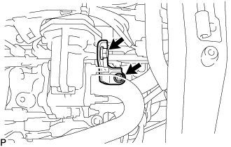
| 12. REMOVE NO. 2 EGR PIPE |
Remove the bolt, 4 nuts and No. 2 EGR pipe from the electric EGR control valve assembly and intake manifold.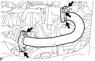
Remove the 2 gaskets.
| 13. REMOVE NO. 1 EGR PIPE SUB-ASSEMBLY |
Remove the bolt and disconnect the No. 1 EGR pipe sub-assembly from the vacuum transmitting pipe sub-assembly.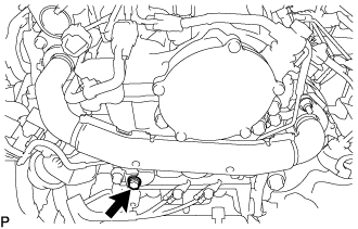
Remove the 4 nuts and the No. 1 EGR pipe sub-assembly from the exhaust manifold and EGR valve adapter.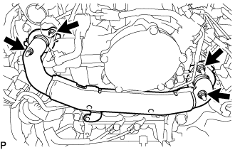
Remove the 2 gaskets.
Using an E8 "TORX" socket wrench, remove the 2 stud bolts from the exhaust manifold.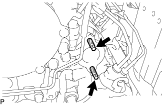
| 14. REMOVE VACUUM CONTROL VALVE SET |
Disconnect the connector from the vacuum control valve set.
Disconnect the 2 vacuum hoses from the vacuum control valve set and No. 2 EGR valve assembly.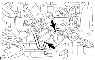
Remove the 2 bolts and vacuum control valve set from the intake manifold.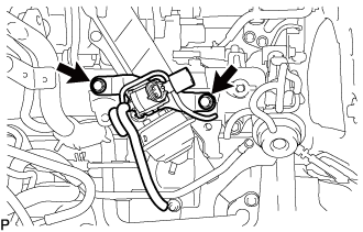
| 15. REMOVE NO. 1 EGR COOLER AND NO. 2 EGR VALVE ASSEMBLY WITH ELECTRIC EGR CONTROL VALVE ASSEMBLY |
Remove the 4 bolts and No. 1 EGR cooler and No. 2 EGR valve assembly with electric EGR control valve assembly from the intake manifold.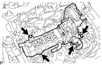
| 16. REMOVE WIRING HARNESS CLAMP BRACKET |
Disconnect the pressure discharge valve connector from the common rail assembly.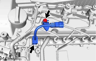
Remove the bolt and wiring harness clamp bracket from the cylinder head cover sub-assembly.
| 17. REMOVE HARNESS BRACKET |
Remove the bolt and harness bracket.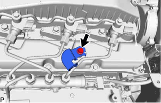
| 18. REMOVE NO. 1 FUEL PIPE |
Remove the bolt, union bolt and gasket and disconnect the No. 1 fuel pipe from the cylinder head cover sub-assembly and exhaust fuel addition injector assembly.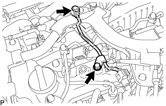
Disconnect the No. 4 fuel pipe and remove the No. 1 fuel pipe (Click here).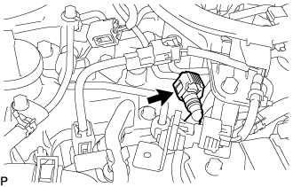
| 19. REMOVE NOZZLE LEAKAGE PIPE ASSEMBLY |
Slide the clamp and disconnect the No. 5 fuel hose from the nozzle leakage pipe assembly.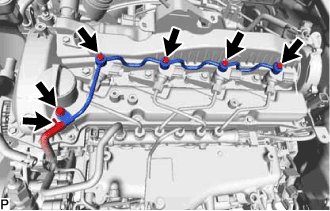
Remove the 4 union bolts and 4 gaskets.
Remove the bolt and nozzle leakage pipe assembly.
| 20. REMOVE NO. 1 INJECTION PIPE SUB-ASSEMBLY AND NO. 2 INJECTION PIPE SUB-ASSEMBLY |
- NOTICE:
- After removing the No. 1 and No. 2 injection pipe sub-assemblies, cover the common rail assembly with electrical tape to prevent dirt or foreign objects from entering the pipe inlet. Also, protect the injector inlets with electrical tape or plastic bags.
Using SST, loosen the No. 1 and No. 2 injection pipe sub-assemblies and 8 union nuts of the fuel injector assembly side and common rail assembly side.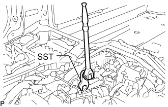
- SST
- 09245-11010
Remove the 2 No. 1 injection pipe sub-assemblies and 2 No. 2 injection pipe sub-assemblies.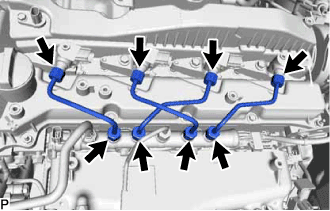
- NOTICE:
- When removing the No. 1 injection pipe sub-assembly and No. 2 injection pipe sub-assembly, store the injector assemblies in the correct order so that they can be returned to their original locations when reassembling.
| 21. REMOVE INJECTOR ASSEMBLY |
Remove the 4 nozzle holder clamp bolts, 4 washers and 4 nozzle holder clamps.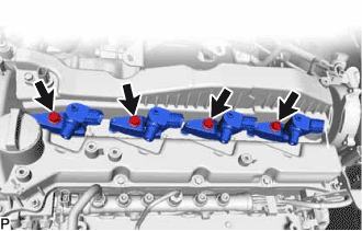
Remove the 4 fuel injector assemblies and 4 injection nozzle seats from the cylinder head sub-assembly.
- NOTICE:
- When removing the injector assembly, store the injector assemblies in the correct order so that they can be returned to their original locations when reassembling.
Remove the O-ring from each injector assembly.
| 22. REMOVE NOZZLE HOLDER GASKET |
Remove the 4 nozzle holder gaskets from the cylinder head cover sub-assembly.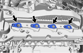
| 23. DISCONNECT BRACKET |
Detach the 3 clamps and disconnect the 2 connectors from the bracket.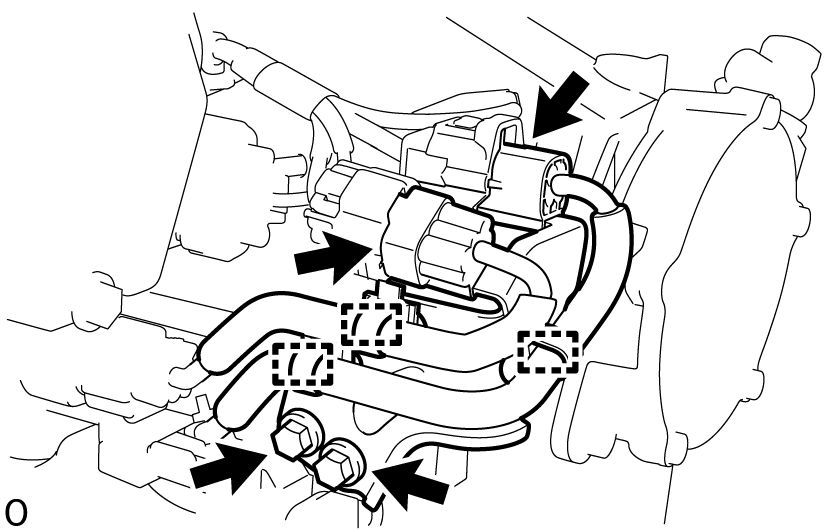
Remove the 2 bolts and disconnect the bracket from the cylinder head sub-assembly.
| 24. REMOVE CAMSHAFT POSITION SENSOR |
Disconnect the camshaft position sensor connector.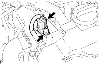
Remove the bolt and camshaft position sensor from the cylinder head cover sub-assembly.
| 25. REMOVE VACUUM PUMP ASSEMBLY |
Disconnect the No. 1 vacuum transmitting hose sub-assembly from the vacuum pump assembly.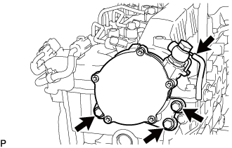
Remove the 3 bolts and vacuum pump assembly from the cylinder head sub-assembly.
Remove the 2 O-rings from the vacuum pump assembly.
| 26. REMOVE CAMSHAFT OIL SEAL RETAINER |
Remove the camshaft oil seal retainer from the No. 3 camshaft bearing cap and cylinder head sub-assembly.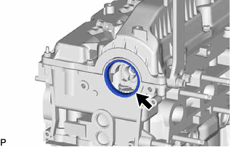
| 27. REMOVE CYLINDER HEAD COVER SUB-ASSEMBLY |
Remove the 14 bolts, 4 nozzle holder clamp seats, 2 nuts and cylinder head cover sub-assembly from the cylinder head sub-assembly.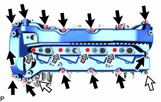
Text in Illustration 
Bolt

Nut

Nozzle Holder Clamp Seat
Remove the cylinder head cover gasket, No. 2 cylinder head cover gasket and 2 camshaft bearing cap oil hole gaskets from the cylinder head cover sub-assembly.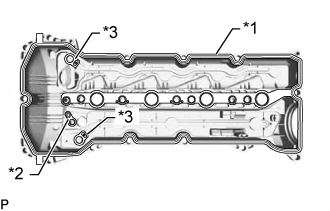
Text in Illustration *1
Cylinder Head Cover Gasket
*2
No. 2 Cylinder Head Cover Gasket
*3
Camshaft Bearing Cap Oil Hole Gasket
| 28. SET NO. 1 CYLINDER TO TDC/COMPRESSION |
Align the timing mark of the crankshaft pulley and timing chain cover by rotating the crankshaft clockwise.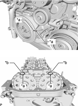
Text in Illustration *a
Timing Mark
*b
Paint Mark
Make sure that the timing mark of the camshaft timing sprocket is at the top.
- HINT:
- If the timing mark is not at the top, turn the crankshaft pulley 1 revolution so that the timing mark is at the top (set the No. 1 piston to TDC/ compression).
Place paint marks on the No. 2 chain sub-assembly.
| 29. REMOVE TIMING CHAIN GUIDE |
Remove the bolt and timing chain guide from the cylinder head sub-assembly.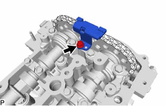
| 30. REMOVE CAMSHAFT |
Remove the oil pump relief valve plug and gasket from timing chain cover.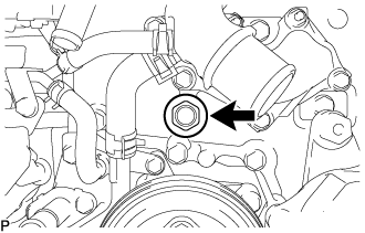
Insert a pin into stopper plate hole of the No. 2 chain tensioner assembly and lock the No. 2 chain tensioner assembly.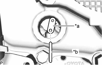
Text in Illustration *a
Stopper Plate
*b
Pin
Hold the hexagonal portion of the camshaft with a wrench and loosen the 2 bolts from the No. 1 camshaft and No. 2 camshaft.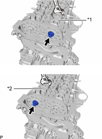
Text in Illustration *1
No. 1 Camshaft
*2
No. 2 Camshaft
- CAUTION:
- Be careful not to damage the cylinder head sub-assembly with the wrench.
Remove the 2 bolts and No. 3 camshaft bearing cap from the cylinder head sub-assembly.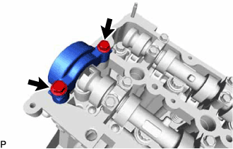
Using several steps, and remove the 20 bolt, No. 1 camshaft bearing cap and 8 No. 2 camshaft bearing caps from the cylinder head sub-assembly.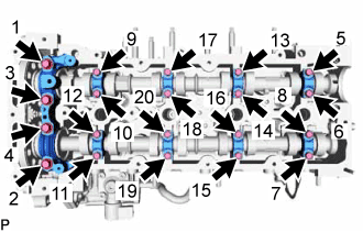
Raise the No. 1 camshaft and remove the bolt from the No. 1 camshaft.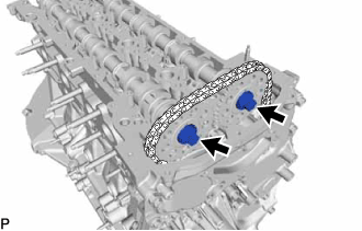
Raise the No. 2 camshaft and remove the bolt from the No. 2 camshaft.
Remove the No. 2 camshaft from the camshaft timing sprocket.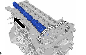
Remove the camshaft timing sprocket from the No. 2 chain sub-assembly.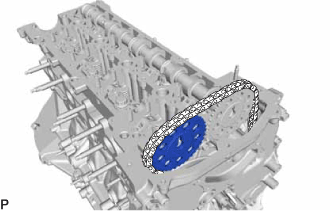
Remove the No. 1 camshaft from the camshaft timing sprocket.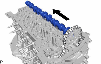
Remove the camshaft timing sprocket from the No. 2 chain sub-assembly.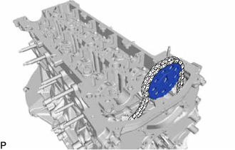
Suspend the No. 2 chain sub-assembly with a string or equivalent.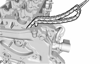
- HINT:
- Be careful not to drop the No. 2 chain sub-assembly inside the timing chain cover assembly.