REMOVAL
Removal / installation · Vehicles built from Oct 2014
| 1. REMOVE NO. 1 ENGINE UNDER COVER (for Cold Area Specification Vehicles) |

Remove the 4 bolts and No. 1 engine under cover.
| 2. REMOVE NO. 2 ENGINE UNDER COVER (for Cold Area Specification Vehicles) |
Remove the 6 bolts and No. 2 engine under cover.
| 3. DRAIN ENGINE COOLANT |
- CAUTION:
- Do not remove the radiator reservoir cap sub-assembly while the engine and radiator are still hot. Pressurized, hot engine coolant and steam may be released and cause serious burns.
Loosen the radiator drain cock plug.
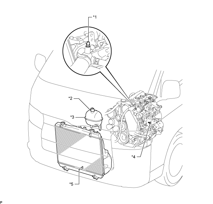

Text in Illustration *1
Bleeder Plug
*2
Radiator Reservoir Cap Sub-assembly
*3
Radiator Reservoir Assembly
*4
Cylinder Block Drain Cock Plug
*5
Radiator Drain Cock Plug
-
-
Remove the radiator reservoir cap sub-assembly.
Loosen the cylinder block drain cock plug (on the engine oil cooler cover), and drain the engine coolant.
Tighten the radiator drain cock plug.
Tighten the cylinder block drain cock plug (on the engine oil cooler cover).
- Torque:
- 8.0 N*m{ 82 kgf*cm , 71 in.*lbf }
| 4. REMOVE NO. 2 ENGINE SERVICE HOLE COVER (for Standard Body) |
| 5. REMOVE TRANSMISSION OIL FILLER TUBE SUB-ASSEMBLY (for Automatic Transmission) |
Remove the 2 bolts and transmission oil filler tube sub-assembly.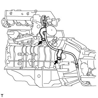
Remove the O-ring from the oil filler tube sub-assembly.
| 6. REMOVE DIESEL THROTTLE BODY ASSEMBLY |
| 7. REMOVE ENGINE OIL LEVEL DIPSTICK GUIDE |
Remove the bolt and engine oil level dipstick guide.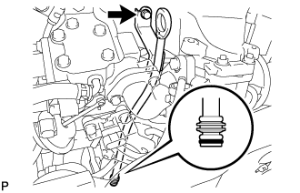
Remove the O-ring from the engine oil level dipstick guide.
| 8. DISCONNECT NO. 1 GAS FILTER |
Remove the bolt and disconnect the vacuum hose together with the No. 1 gas filter.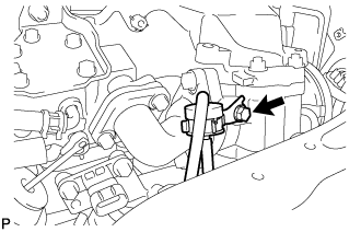
| 9. REMOVE VACUUM SWITCHING VALVE ASSEMBLY |
Disconnect the connector from the electric EGR control valve.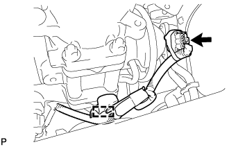
Detach the clamp and wire harness.
Disconnect the connector and vacuum hose from the vacuum switching valve.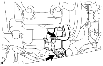
Remove the bolt and vacuum switching valve.
| 10. REMOVE MANIFOLD STAY |
Remove the 2 bolts and manifold stay.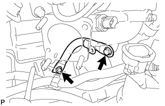
| 11. REMOVE ELECTRIC EGR CONTROL VALVE ASSEMBLY |
Remove the 2 bolts and disconnect the No. 2 EGR pipe from the No. 2 EGR valve and gasket.
Remove the bolt and 2 nuts, disconnect the electric EGR control valve together with the intake air connector from the intake manifold and remove the gasket.
Remove the electric EGR control valve and gasket from the intake air connector.
Disconnect the connector from the vacuum regulating valve.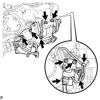
Disconnect the 2 vacuum hoses from the vacuum regulating valve.
Remove the 2 bolts and vacuum regulating valve.
| 12. DISCONNECT NO. 4 VACUUM TRANSMITTING HOSE ASSEMBLY |
Disconnect the No. 4 vacuum transmitting hose from the EGR cooler.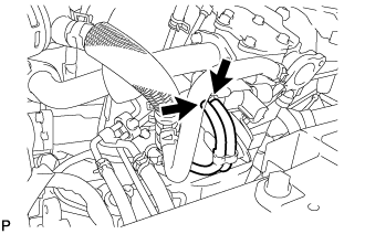
| 13. DISCONNECT WATER BY-PASS HOSE ASSEMBLY |
Disconnect the water by-pass hose from the EGR cooler.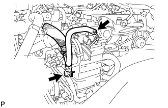
| 14. DISCONNECT NO. 4 WATER BY-PASS HOSE |
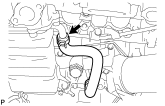 |
| 15. REMOVE EGR COOLER ASSEMBLY |
Remove the 2 bolts, 2 nuts and No. 1 EGR pipe together with the No. 2 EGR valve and EGR cooler.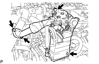
Remove the gasket from the cylinder head.
| 16. REMOVE NO. 1 EGR PIPE SUB-ASSEMBLY |
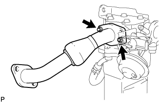
Remove the 2 nuts, No. 1 EGR pipe and gasket.