INSTALLATION
Removal / installation · Vehicles built from Jan 2017
| 1. INSTALL EXHAUST GAS TEMPERATURE SENSOR |

Using a 14 mm union nut wrench, install the No. 3 exhaust gas temperature sensor to the exhaust manifold converter sub-assembly.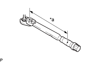

- Torque:
- Specified tightening torque
- 30 N*m {306 kgf*cm, 22 ft.*lbf}
Text in Illustration *a
Torque Wrench Fulcrum Length
- NOTICE:
- If the No. 3 exhaust gas temperature sensor is dropped, replace it with a new.
- When reusing the No. 3 exhaust gas temperature sensors, clean the screws and apply anti-seize compound before installing the No. 3 exhaust gas temperature sensor.
- If the No. 3 exhaust gas temperature sensor is dropped, replace it with a new.
- HINT:
- The connector color of the No. 3 exhaust gas temperature sensor is gray.
- Calculate the torque wrench reading when changing the fulcrum length of the torque wrench (Click here).
- When using a union nut wrench (fulcrum length of 25 mm (0.984 in.)) + torque wrench (fulcrum length of 180 mm (7.09 in.)): 26 N*m (268 kgf*cm, 19 ft.*lbf)
- The connector color of the No. 3 exhaust gas temperature sensor is gray.
Using a 14 mm union nut wrench, install the No. 2 exhaust gas temperature sensor to the exhaust manifold converter sub-assembly.
- Torque:
- Specified tightening torque
- 30 N*m {306 kgf*cm, 22 ft.*lbf}
Text in Illustration *a
Torque Wrench Fulcrum Length
- NOTICE:
- If the No. 2 exhaust gas temperature sensor is dropped, replace it with a new.
- When reusing the No. 2 exhaust gas temperature sensors, clean the screws and apply anti-seize compound before installing the No. 2 exhaust gas temperature sensor.
- If the No. 2 exhaust gas temperature sensor is dropped, replace it with a new.
- HINT:
- The connector color of the No. 2 exhaust gas temperature sensor is black.
- Calculate the torque wrench reading when changing the fulcrum length of the torque wrench (Click here).
- When using a union nut wrench (fulcrum length of 25 mm (0.984 in.)) + torque wrench (fulcrum length of 180 mm (7.09 in.)): 26 N*m (268 kgf*cm, 19 ft.*lbf)
- The connector color of the No. 2 exhaust gas temperature sensor is black.
Using a 14 mm union nut wrench, install the exhaust gas temperature sensor to the exhaust manifold converter sub-assembly.
- Torque:
- Specified tightening torque
- 30 N*m {306 kgf*cm, 22 ft.*lbf}
Text in Illustration *a
Torque Wrench Fulcrum Length
- NOTICE:
- If the exhaust gas temperature sensor is dropped, replace it with a new.
- When reusing the exhaust gas temperature sensors, clean the screws and apply anti-seize compound before installing the exhaust gas temperature sensor.
- If the exhaust gas temperature sensor is dropped, replace it with a new.
- HINT:
- The connector color of the exhaust gas temperature sensor is white.
- Calculate the torque wrench reading when changing the fulcrum length of the torque wrench (Click here).
- When using a union nut wrench (fulcrum length of 25 mm (0.984 in.)) + torque wrench (fulcrum length of 180 mm (7.09 in.)): 26 N*m (268 kgf*cm, 19 ft.*lbf)
- The connector color of the exhaust gas temperature sensor is white.
Attach the 3 colored connectors to the pipe clamp in the positions shown in the illustration.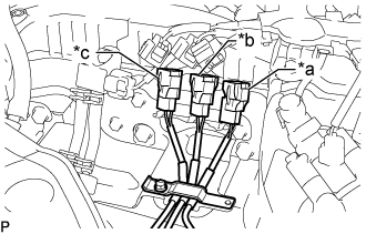
Text in Illustration *a
White
*b
Black
*c
Gray
Close the clamp of the pipe clamp, and install the bolt.
- Torque:
- 10 N*m{ 102 kgf*cm , 7 ft.*lbf }
- NOTICE:
- Arrange the exhaust gas temperature sensor wires so that they do not contact each other.
Connect the No. 3 exhaust gas temperature sensor to the No. 1 vacuum pipe.
- Torque:
- 10 N*m{ 102 kgf*cm , 7 ft.*lbf }
Connect the 3 connectors to the 3 exhaust gas temperature sensors.
| 2. INSTALL ENGINE ASSEMBLY |
- HINT:
- Perform this procedure only when removal or installation of the No. 3 exhaust gas temperature sensor.
| 3. INSTALL ENGINE SERVICE HOLE SUB COVER SUB-ASSEMBLY |
Install the engine service hole sub cover sub-assembly with the 5 bolts.
- Torque:
- 13 N*m{ 133 kgf*cm , 10 ft.*lbf }
Return the floor carpet to its original position.
| 4. INSTALL FRONT DOOR SCUFF PLATE RH |
| 5. INSTALL FRONT SEAT ASSEMBLY RH |
Connect the front seat inner belt assembly connector and install the front seat assembly.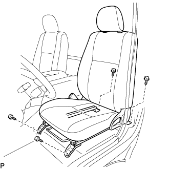
Align the front seat assembly adjuster pin with the holes in the body.
Move the front seat assembly to the rearmost position.
- NOTICE:
- Make sure that the front seat assembly is securely locked.
Temporarily tighten the 2 bolts on the front side of the front seat assembly.
Move the front seat assembly fully forward.
- NOTICE:
- Make sure that the front seat assembly is securely locked.
Temporarily tighten the 2 bolts on the rear side of the front seat assembly.
Move the front seat assembly to the rearmost position.
- NOTICE:
- Make sure that the front seat assembly is securely locked.
Fully tighten the 2 bolts on the front side of the front seat assembly in the order of outer and inner side.
- Torque:
- 39 N*m{ 398 kgf*cm , 29 ft.*lbf }
Move the front seat assembly fully forward.
- NOTICE:
- Make sure that the front seat assembly is securely locked.
Fully tighten the 2 bolts on the rear side of the front seat assembly in the order of outer and inner side.
- Torque:
- 39 N*m{ 398 kgf*cm , 29 ft.*lbf }
| 6. INSTALL SEAT TRACK COVER LH |
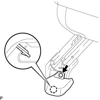
Attach the claw and install a new seat track cover LH with a new clip.