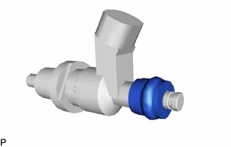
REMOVAL
Removal / installation · Vehicles built from Jan 2017
| 1. DRAIN ENGINE COOLANT |

- CAUTION:
- Do not remove the radiator cap sub-assembly while the engine assembly and radiator assembly are still hot. Pressurized, hot engine coolant and steam may be released and cause serious burns.
Connect a hose with an inside diameter of 9 mm (0.354 in.) to the radiator drain cock.
Loosen the radiator drain cock plug.
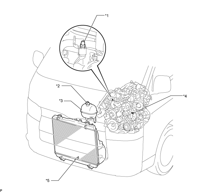

Text in Illustration *1
Bleeder Plug
*2
Radiator Cap Sub-assembly
*3
Radiator Reserve Tank Assembly
*4
Cylinder Block Drain Cock Plug
*5
Radiator Drain Cock Plug
-
-
Remove the radiator cap sub-assembly.
Loosen the cylinder block drain cock plug, and drain the engine coolant.
Tighten the radiator drain cock plug.
Tighten the cylinder block drain cock plug.
- Torque:
- 13 N*m{ 130 kgf*cm , 9 ft.*lbf }
Disconnect the hose from the radiator drain cock.
| 2. REMOVE SEAT TRACK COVER LH |
Using a clip remover, remove the clip.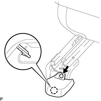
Detach the claw and remove the seat track cover LH.
| 3. REMOVE FRONT SEAT ASSEMBLY RH |
Move the front seat assembly fully forward.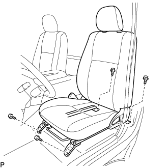
Remove the 2 bolts on the rear side of the seat.
Move the front seat assembly to the rearmost position.
Remove the 2 bolts on the front side of the seat.
Move the front seat assembly to the center of the seat slide rail. Set the seatback in the upright position.
Disconnect the front seat inner belt assembly connector.
Remove the front seat assembly.
| 4. REMOVE FRONT DOOR SCUFF PLATE RH |
| 5. REMOVE ENGINE SERVICE HOLE SUB COVER SUB-ASSEMBLY |
Fold back the floor carpet.
Remove the 5 bolts and engine service hole sub cover sub-assembly.
| 6. REMOVE NO. 1 FUEL PIPE |
Remove the bolt, union bolt and gasket and disconnect the No. 1 fuel pipe from the cylinder head cover sub-assembly and exhaust fuel addition injector assembly.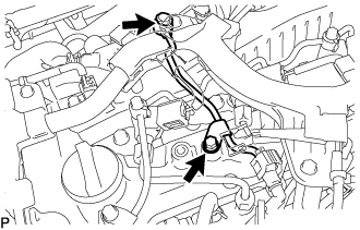
Disconnect the No. 4 fuel pipe and remove the No. 1 fuel pipe (Click here).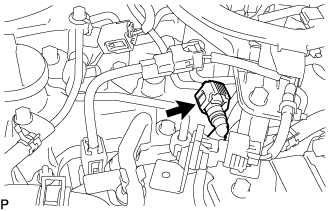
| 7. DISCONNECT NO. 4 WATER BY-PASS HOSE |
Slide the clamp and disconnect the No. 4 water by-pass hose from the No. 1 injector holder.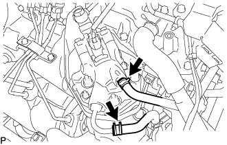
| 8. DISCONNECT NO. 5 WATER BY-PASS HOSE |
Slide the clamp and disconnect the No. 5 water by-pass hose from the No. 1 injector holder.
| 9. REMOVE NO. 1 INJECTOR HOLDER |
Disconnect the connector from the exhaust fuel addition injector assembly.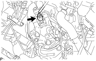
Remove the 3 nuts and No. 1 injector holder from the exhaust manifold.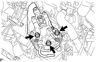
| 10. REMOVE NO. 2 EXHAUST MANIFOLD HEAT INSULATOR |
Remove the 3 nuts and No. 2 exhaust manifold heat insulator from the No. 1 injector holder.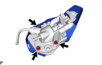
Remove the gasket.
| 11. REMOVE INJECTOR HOLDER |
Remove the 2 bolts and injector holder from the No. 1 injector holder.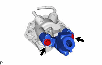
| 12. REMOVE NO. 2 NOZZLE HOLDER CLAMP |
Using a T40 "TORX" socket wrench, remove the bolt and No. 2 nozzle holder clamp from the No. 1 injector holder.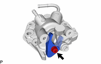
| 13. REMOVE EXHAUST FUEL ADDITION INJECTOR ASSEMBLY |
Remove the exhaust fuel addition injector assembly from the No. 1 injector holder.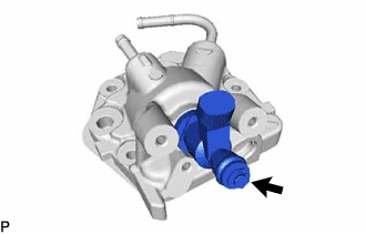
Remove the gasket from the No. 1 injector holder.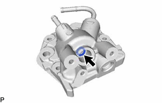
Remove the E-ring from the exhaust fuel addition injector assembly.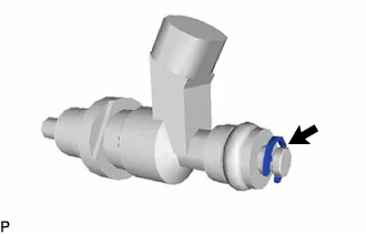
Remove the No. 3 fuel injector back-up ring, O-ring, No. 2 fuel injector back-up ring and No. 1 fuel injector back-up ring from the exhaust fuel addition injector assembly.