INTERIOR PANELS / TRIM INSTRUMENT PANEL SAFETY PAD DISASSEMBLY
CAUTION / NOTICE / HINT
- HINT:
- ·
Use the same procedure for RHD and LHD vehicles.
·The procedure listed below is for LHD vehicles.
PROCEDURE

 55990C
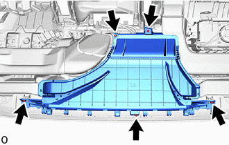
1.REMOVE CENTER DEFROSTER NOZZLE ASSEMBLY

|
Screw <A> |
Remove the 5 screws <A>.
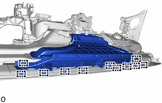
Detach the guide and remove the center defroster nozzle assembly.
55843A
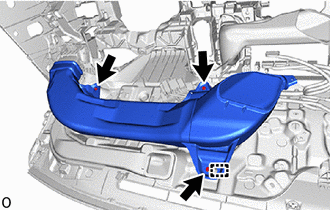
2.REMOVE NO. 1 HEATER TO REGISTER DUCT
|
|
Screw <A> |
Remove the 3 screws <A>.
Detach the guide and remove the No. 1 heater to register duct.
55845A
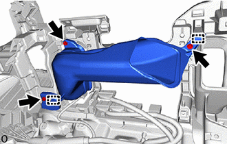
3.REMOVE NO. 3 HEATER TO REGISTER DUCT
|
|
Screw <A> |
Remove the 3 screws <A>.
Detach the guide and remove the No. 3 heater to register duct.
55844
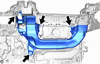
4.REMOVE NO. 2 HEATER TO REGISTER DUCT
|
|
Screw <A> |
Remove the 4 screws <A>.
Detach the guide and remove the No. 2 heater to register duct.
5.REMOVE NAVIGATION ANTENNA ASSEMBLY WITH BRACKET (w/ Navigation Antenna)
86101
6.REMOVE ANTENNA CORD SUB-ASSEMBLY
89120A
7.REMOVE AUTOMATIC LIGHT CONTROL SENSOR (w/ Automatic Light Control System)
88625H
8.REMOVE COOLER (SOLAR SENSOR) THERMISTOR (w/o Automatic Light Control System)
55538C
9.REMOVE COOLER SWITCH HOLE COVER (w/ Cover)
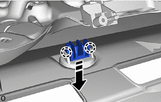

|
Remove in this Direction |
Detach the claw and remove the cooler switch hole cover.
89747F
10.REMOVE BLIND SPOT MONITOR BUZZER (w/ Blind Spot Monitor System)
82144
11.REMOVE NO. 4 INSTRUMENT PANEL WIRE
for LHD:
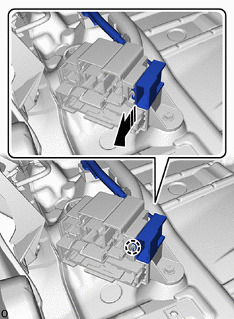
|
|
Remove in this Direction |
Slide in the direction indicated by the arrow shown in the illustration to detach the claw.
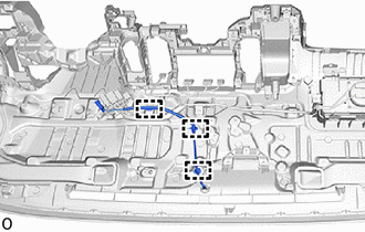
w/ Solar Sensor, w/ Automatic Light Control System:
Detach the clamp and remove the No. 4 instrument panel wire.
w/ Solar Sensor, w/o Automatic Light Control System:
Detach the clamp and remove the No. 4 instrument panel wire.
for RHD:
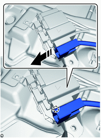
|
|
Remove in this Direction |
Slide in the direction indicated by the arrow shown in the illustration to detach the claw.
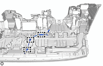
w /Solar Sensor, w/ Automatic Light Control System:
Detach the clamp and remove the No. 4 instrument panel wire.
w /Solar Sensor, w/o Automatic Light Control System:
Detach the clamp and remove the No. 4 instrument panel wire.
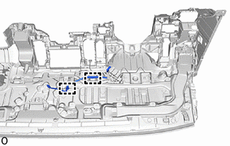
w/ Blind Spot Monitor System:
Detach the clamp and remove the No. 4 instrument panel wire.
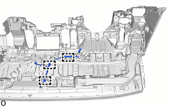
w/ Blind Spot Monitor System, w/ Automatic Light Control System:
Detach the clamp and remove the No. 4 instrument panel wire.
73960A
12.REMOVE INSTRUMENT PANEL PASSENGER AIRBAG ASSEMBLY (w/ Front Passenger Airbag)
73908
13.REMOVE INSTRUMENT PANEL PASSENGER AIRBAG CASE SUB-ASSEMBLY (w/o Front Passenger Airbag)
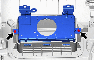
|
|
Screw <A> |
Remove the 2 screws <A>.
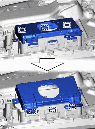
Lean the instrument panel safety pad sub-assembly and detach the hook.
Detach the hook to remove the instrument panel passenger airbag case sub-assembly.
82142A
14.REMOVE NO. 2 INSTRUMENT PANEL WIRE
for LHD:
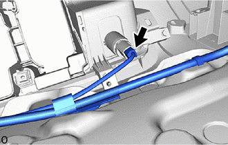
Disconnect the connector.
Remove the screw.
Detach the clamp and remove the No. 2 instrument panel wire.
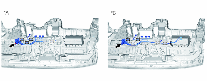
| *A | w/o Front Passenger Airbag | *B | w/ Front Passenger Airbag |
for RHD:
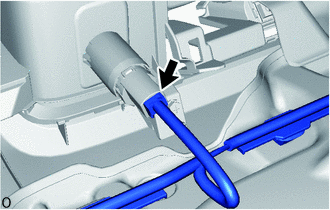
Disconnect the connector.
Remove the screw.
Detach the clamp and remove the No. 2 instrument panel wire.
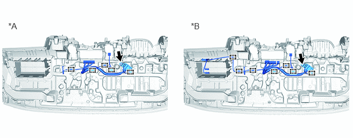
| *A | w/o Front Passenger Airbag | *B | w/ Front Passenger Airbag |
55620
15.REMOVE INSTRUMENT PANEL CUP HOLDER ASSEMBLY
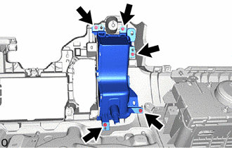
|
|
Screw <A> |
Remove the 5 screws <A>.
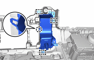
Detach the claw and guide and remove the instrument panel cup holder assembly.
55972C
16.REMOVE NO. 2 SIDE DEFROSTER NOZZLE DUCT
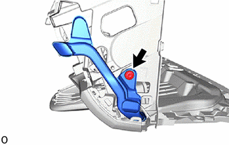
|
|
Clip <H> |
Remove the clip <H> and No. 2 side defroster nozzle duct.
55316A
17.REMOVE UPPER INSTRUMENT SIDE PATCH LH
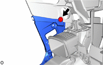
|
|
Clip <H> |
Remove the clip <H>.
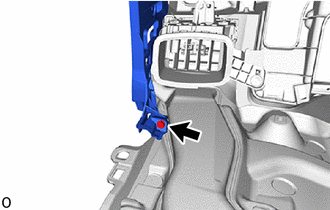
|
|
Screw <A> |
Remove the screw <A>.
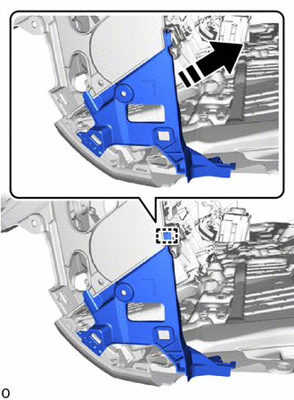
|
|
Remove in this Direction |
Detach the guide and remove the upper instrument side patch LH as shown in the illustration.
55660
18.REMOVE NO. 2 INSTRUMENT PANEL REGISTER ASSEMBLY
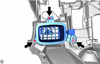
|
|
Screw <A> |
Remove the 3 screws <A>.
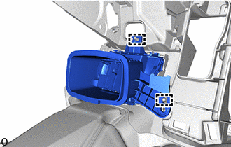
Detach the guide and remove the No. 2 instrument panel register assembly.
55971C
19.REMOVE NO. 1 SIDE DEFROSTER NOZZLE DUCT
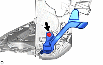
|
|
Clip <H> |
Remove the clip <H> and No. 1 side defroster nozzle duct.
55315C
20.REMOVE UPPER INSTRUMENT SIDE PATCH RH
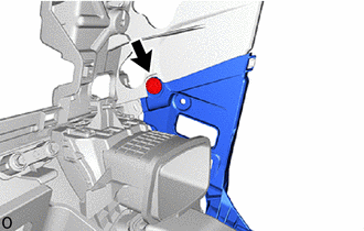
|
|
Clip <H> |
Remove the clip <H>.
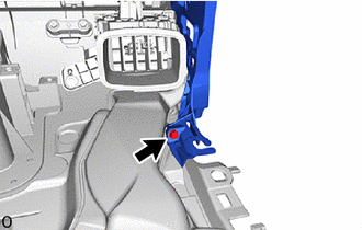
|
|
Screw <A> |
Remove the screw <A>.
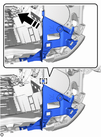
|
|
Remove in this Direction |
Detach the guide and remove the upper instrument side patch RH as shown in the illustration.
55650
21.REMOVE NO. 1 INSTRUMENT PANEL REGISTER ASSEMBLY
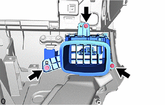
|
|
Screw <A> |
Remove the 3 screws <A>.
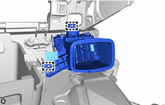
Detach the guide and remove the No. 2 instrument panel register assembly.
55355
22.REMOVE NO. 1 INSTRUMENT PANEL CUSHION (for Full-trim)
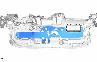
Remove the No. 1 instrument panel cushion.
55356C
23.REMOVE NO. 2 INSTRUMENT PANEL CUSHION (for Full-trim)
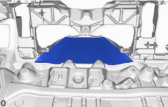
Remove the No. 2 instrument panel cushion.
55357B
24.REMOVE NO. 3 INSTRUMENT PANEL CUSHION (for Full-trim)
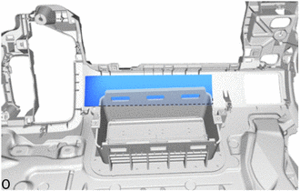
Remove the No. 3 instrument panel cushion.
55471C
25.REMOVE INSTRUMENT PANEL NAME PLATE (w/o Front Passenger Airbag)
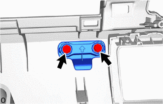
|
|
Screw <A> |
Remove the 2 screws <A>.
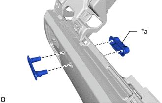
| *a | No. 4 Instrument Panel Safety Pad Retainer |
Remove the No. 4 instrument panel safety pad retainer and instrument panel name plate.
55962D
26.REMOVE NO. 2 SIDE DEFROSTER NOZZLE
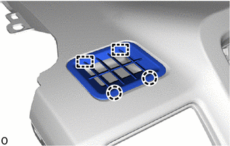
Detach the claw and guide and remove the No. 2 side defroster nozzle.
55961B
27.REMOVE NO. 1 SIDE DEFROSTER NOZZLE
- HINT:
-
Use the same procedure for the No. 2 side defroster nozzle.
55328
28.REMOVE NO. 1 INSTRUMENT PANEL PIN
- HINT:
-
Use the same procedure for the opposite side.
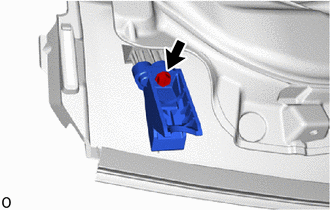
|
|
Screw <A> |
Remove the screw <A>.
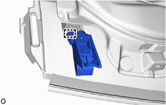
Detach the guide and remove the No. 1 instrument panel pin.
55349A
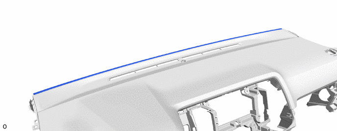
29.REMOVE INSTRUMENT PANEL CUSHION
Remove the instrument panel cushion.
55532B
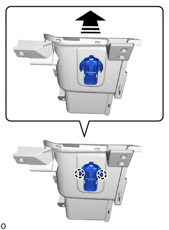
30.REMOVE CIGAR LIGHTER HOLE COVER (w/o Power Outlet Socket)
|
|
Remove in this Direction |
Detach the claw and remove the cigar lighter hole cover as shown in the illustration.
86211
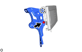
31.REMOVE NO. 1 RADIO BRACKET (w/ Radio Receiver Opening Cover)
|
|
Screw <A> |
Remove the screw <A>.
Detach the claw and remove the No. 1 radio bracket.
86212
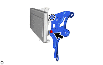
32.REMOVE NO. 2 RADIO BRACKET (w/ Radio Receiver Opening Cover)
|
|
Screw <A> |
Remove the screw <A>.
Detach the claw and remove the No. 2 radio bracket.
55473A
33.REMOVE INSTRUMENT PANEL FINISH PANEL RETAINER (for Full-trim)
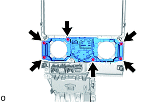
Remove the 6 screws and instrument panel finish panel retainer.
55618B
34.REMOVE NO. 3 SWITCH HOLE BASE (for Full-trim)
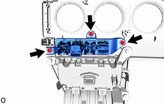
Remove the 3 screws and No. 3 switch hole base.
55539
35.REMOVE SPARE SWITCH HOLE COVER (for Semi-trim)
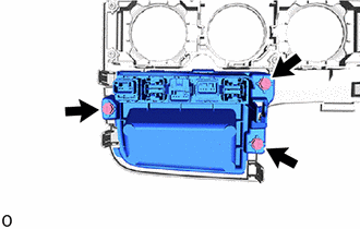
|
|
Screw <A> |
Remove the 3 screws <A> and spare switch hole cover.
55308D
36.REMOVE CENTER INSTRUMENT PANEL BOX SUB-ASSEMBLY (for Full-trim)
55414A
37.REMOVE INSTRUMENT CLUSTER FINISH PANEL END (w/ Radio Receiver Opening Cover)
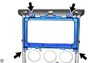
|
|
Screw <A> |
Remove the 4 screws <A> and instrument cluster finish panel end.
38.REMOVE GLOVE COMPARTMENT DOOR LOCK CYLINDER ASSEMBLY
for LHD:
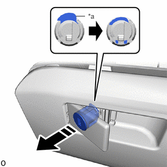
| *a | Stopper |
|
|
Remove in this Direction |
Push the stopper to release the lock, and then push the glove compartment door lock cylinder assembly and remove it from the glove compartment door assembly.
for RHD:
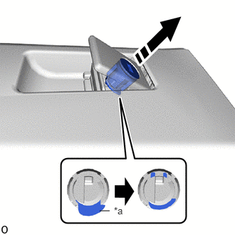
| *a | Stopper |
|
|
Remove in this Direction |
Push the stopper to release the lock, and then push the glove compartment door lock cylinder assembly and remove it from the glove compartment door assembly.
55550
39.REMOVE GLOVE COMPARTMENT DOOR ASSEMBLY
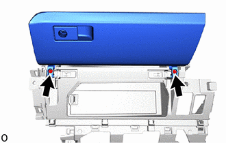
Remove the 2 screws and glove compartment door assembly.
55557A
40.REMOVE GLOVE COMPARTMENT DOOR CHECK CUSHION
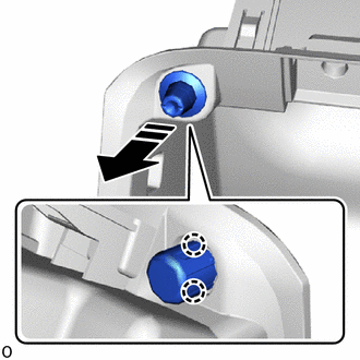
|
|
Remove in this Direction |
Detach the claw and remove the glove compartment door check cushion.
- HINT:
-
Use the same procedure to remove the glove compartment door check cushion on the other side.
55524H
41.REMOVE SWITCH BASE HOLE COVER (for RHD, w/ Console Tray)
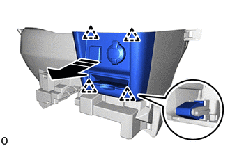
|
|
Remove in this Direction |
Detach the clip and remove the switch base hole cover.
55548A
42.REMOVE INSTRUMENT PANEL HOLE COVER (for RHD, w/Console Tray)
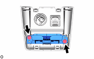
Remove the 2 screws.
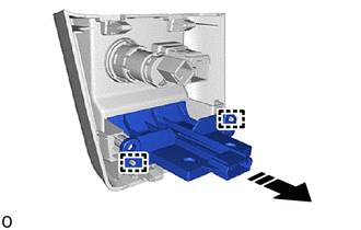
|
|
Remove in this Direction |
Detach the guide and remove the instrument panel hole cover.