TELEMATICS TELEPHONE ANTENNA REMOVAL
CAUTION / NOTICE / HINT
The necessary procedures (adjustment, calibration, initialization or registration) that must be performed after parts are removed, installed or replaced during the No. 2 amplifier antenna assembly removal/installation are shown below.
| Replacement Part or Procedure | Necessary Procedures | Effect/Inoperative Function When Necessary Procedures are not Performed | Link |
|---|---|---|---|
| Disconnect cable from negative (-) battery terminal | Memorize steering angle neutral point | Parking assist monitor system | ( ) |
- HINT:
-
When the cable is disconnected/reconnected to the battery terminal, systems temporarily stop operating. However, each system has a function that completes learning the first time the systems is used.
- ·
Learning completes when vehicle is operated normally
Effect/Inoperative Function When Necessary Procedures are not Performed Necessary Procedures Link Air conditioning system After the ignition switch is turned to ON, the servo motor standard position is recognized. -
PROCEDURE

 1. PRECAUTION
- CAUTION:
-
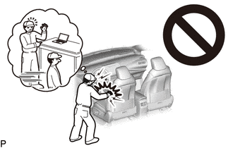
-
Be sure to read Precaution thoroughly before servicing.
- ·
for Type A:
Click hereVehicle Interior>SUPPLEMENTAL RESTRAINT SYSTEMS>AIRBAG SYSTEM (for Type A)>PRECAUTION
·for Type B:
Click hereVehicle Interior>SUPPLEMENTAL RESTRAINT SYSTEMS>AIRBAG SYSTEM (for Type B)>PRECAUTION
- NOTICE:
-
After turning the ignition switch off, waiting time may be required before disconnecting the cable from the negative (-) battery terminal.
-
Click hereGeneral>SETUP>WHEN DISCONNECTING OR RECONNECTING BATTERY TERMINAL>BEFORE DISCONNECTING BATTERY
2.DISCONNECT CABLE FROM NEGATIVE BATTERY TERMINAL
Click hereGeneral>MAINTENANCE>1GD-FTV BATTERY>REMOVAL
- CAUTION:
-
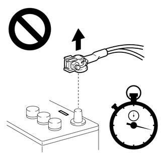
- ·
Wait at least 90 seconds after disconnecting the cable from the negative (-) battery terminal to disable the SRS system.
·If the airbag deploys for any reason, it may cause a serious accident.
3.REMOVE ROOF HEADLINING ASSEMBLY
86300C
4.REMOVE NO. 2 AMPLIFIER ANTENNA ASSEMBLY
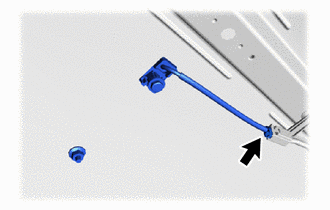
Disconnect the connector.
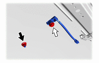

|
Nut |

|
Bolt |
Remove the nut and bolt.
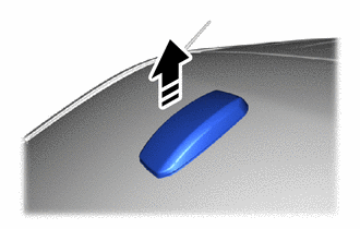

|
Remove in this Direction |
Remove the No. 2 amplifier antenna assembly as shown in the illustration.