LIGHTING (INT) LIGHTING SYSTEM Interior Light Circuit
DESCRIPTION
The main body ECU (multiplex network body ECU) controls the operation of the following lights:
Transponder key coil*1
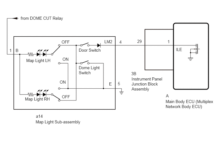
Map light sub-assembly*2, *5
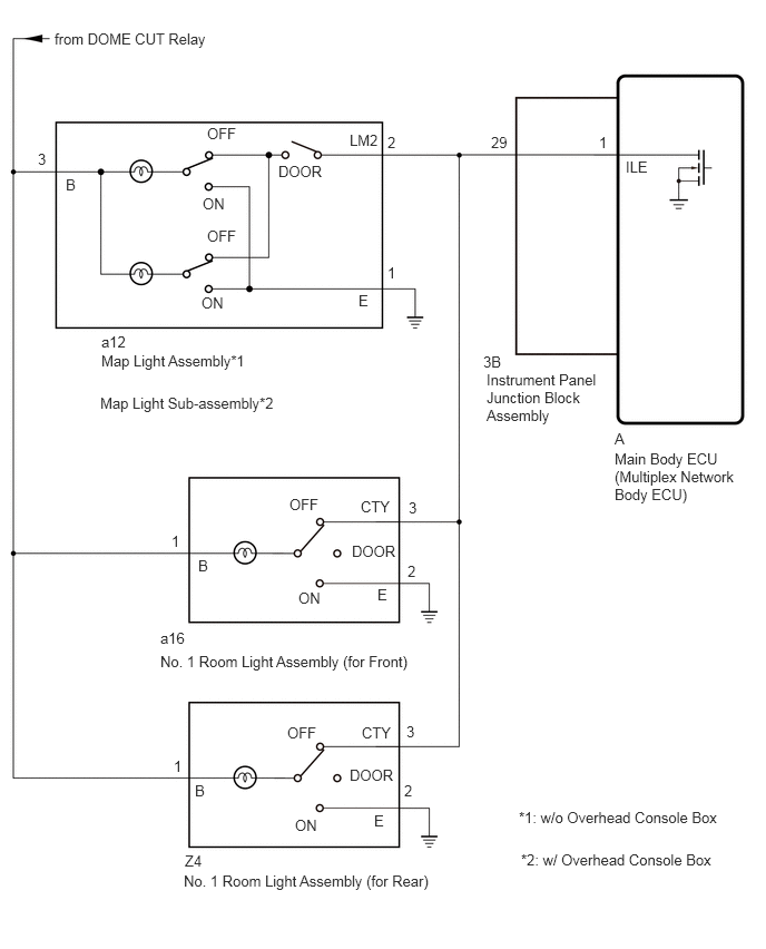
Map light assembly*3, *4
No. 1 room light assembly (for Front)*3
No. 1 room light assembly (for Rear)*3
*1: w/ Immobiliser System
*2: for LED Type
*3: for Bulb Type
*4: w/o Overhead Console
*5: w/ Overhead Console
WIRING DIAGRAM
for LED Type
for Bulb Type
PROCEDURE
Perform the Active Test according to the display on the GTS.
Click hereVehicle Interior>LIGHTING (INT)>LIGHTING SYSTEM>DATA LIST / ACTIVE TEST
- Body Electrical > Main Body > Active Test
-
Tester Display Measurement Item Control Range Diagnostic Note Illuminated Entry System Turns on the lights that are controlled by the illuminated entry system* OFF or ON Perform the Active Test with DOOR switch is turned on.
- Body Electrical > Main Body > Active Test
-
Tester Display Illuminated Entry System - 50004 123 4
*: Refer to Operation Check for the lights that are controlled by the illuminated entry system.
Click hereVehicle Interior>LIGHTING (INT)>LIGHTING SYSTEM>OPERATION CHECK
- OK:
Map light sub-assembly and transponder key coil turn on or off.
- Result:
Proceed to OK NG
OK
NG
*1: for LED Type
*2: for Bulb Type
*3: w/o Overhead Console Box
*4: w/ Overhead Console Box
Disconnect the a12*1or a14*2 map light assembly*3 or map light sub-assembly*4 connector.
Disconnect the a16 No. 1 room light assembly (for Front) connector.*2
Disconnect the Z4 No. 1 room light assembly (for Rear) connector.*2
Disconnect the 3B instrument panel junction block assembly connector.
Measure the resistance according to the value(s) in the table below.
- Standard Resistance:
for LED Type: Tester Connection Condition Specified Condition a14-4 (LM2) - 3B-29 Always Below 1 Ω
for Bulb Type: Tester Connection Condition Specified Condition a12-2 (LM2) - 3B-29 Always Below 1 Ω
- Result:
Proceed to OK NG
OK
NG
Remove the instrument panel junction block assembly.
for LHD:
Click herePower Source / Network>POWER DISTRIBUTION>MAIN BODY ECU (for LHD)>REMOVAL
for RHD:
Click herePower Source / Network>POWER DISTRIBUTION>MAIN BODY ECU (for RHD)>REMOVAL
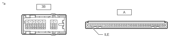
| *a | Component without harness connected
(Instrument Panel Junction Block Assembly) |
- | - |
Remove the main body ECU (multiplex network body ECU) from the instrument panel junction block assembly.
for LHD:
Click herePower Source / Network>POWER DISTRIBUTION>MAIN BODY ECU (for LHD)>REMOVAL
for RHD:
Click herePower Source / Network>POWER DISTRIBUTION>MAIN BODY ECU (for RHD)>REMOVAL
Measure the resistance according to the value(s) in the table below.
- Standard Resistance:
Tester Connection Condition Specified Condition 3B-29 - A-1 (ILE) Always Below 1 Ω
- Result:
Result Proceed to OK (for LHD) A OK (for RHD) B NG (for LHD) C NG (for RHD) D
A
B
C
D