SEAT FRONT SEAT ASSEMBLY(for Sliding Bench Seat Type) REASSEMBLY
CAUTION / NOTICE / HINT
- CAUTION:
- ·
Wear protective gloves. Sharp areas on the parts may injure your hands.
·There is risk of injury.
- HINT:
- ·
Use the same procedure for RHD and LHD vehicles.
·The procedure listed below is for LHD vehicles.
PROCEDURE

 72211F
1.INSTALL SEAT TRACK ADJUSTING HANDLE RH
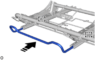

|
Install in this Direction |
Attach the guide and install the seat track adjusting handle RH as shown in the illustration.
2.INSTALL FRONT SEATBACK ASSEMBLY RH
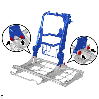
Install the front seatback assembly RH with the 4 bolts.
- Torque:
- 42 N*m (428 kgf*cm, 31 ft.*lbf)
72580C
3.INSTALL RH SEAT RECLINING ADJUSTING CABLE ASSEMBLY
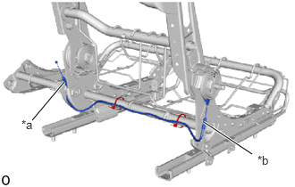
| *a | Pink Cable Color |
| *b | White Cable Color |
Install the RH seat reclining adjusting cable assembly with 2 new cable ties.
Cut off the end of the cable tie.
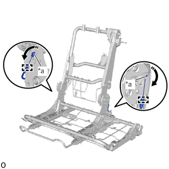
| *a | Cable End |
|
|
Move in this Direction |
Connect the 2 cable ends by moving them in the direction of the arrows in the illustration.
Attach the cable clamp.
71H76
4.INSTALL RH SEAT RECLINING ADJUSTER INSIDE COVER RH
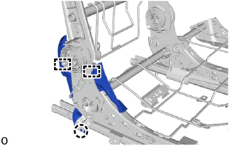
Attach the guide and claw and install the RH seat reclining adjuster inside cover RH.
71H75A
5.INSTALL RH SEAT RECLINING ADJUSTER INSIDE COVER
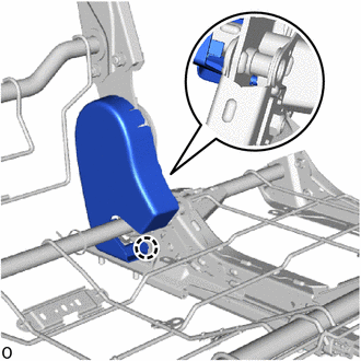
Attach the claw and install the RH seat reclining adjuster inside cover.
71862M
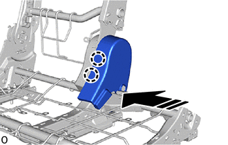
6.INSTALL FRONT SEAT INNER NO. 2 CUSHION SHIELD LH
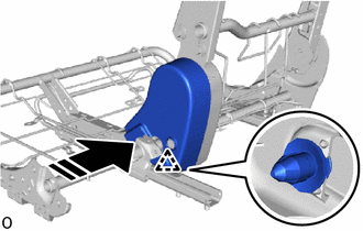
|
|
Install in this Direction |
Attach the clip as shown in the illustration.
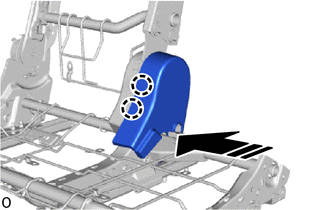
|
|
Install in this Direction |
Attach the claw as shown in the illustration.
|
|
Install in this Direction |
Attach the claw and install the front seat inner No. 2 cushion shield LH as shown in the illustration.
73187
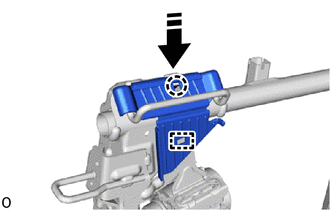
7.INSTALL FRONT SEAT SHOULDER BELT GUIDE
|
|
Install in this Direction |
Attach the guide and claw and install the front seat shoulder belt guide as shown in the illustration.
73120
8.INSTALL FRONT SEAT 3 POINT TYPE BELT ASSEMBLY LH
71H75B
9.INSTALL RH SEATBACK FRAME RECLINING ADJUSTER INSIDE COVER
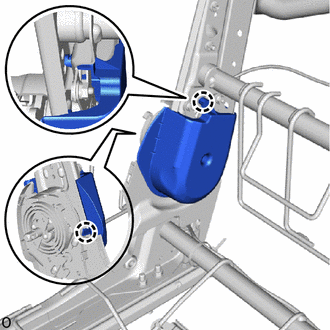
Attach the claw and install the RH seatback frame reclining adjuster inside cover.
89178C
10.INSTALL NO. 2 AIRBAG BRACKET (w/ Front Seat Side Airbag)
73910B
11.INSTALL FRONT SEAT AIRBAG ASSEMBLY RH (w/ Front Seat Side Airbag)
74810L
12.INSTALL FRONT PROTECTOR ASSEMBLY RH
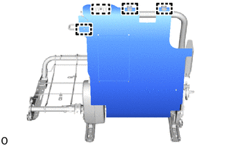
Attach the guide.
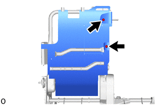
Install the front protector assembly RH with the 2 clips.
71551A
13.INSTALL FRONT SEATBACK PAD RH
Install the front seatback pad RH.
79158
14.INSTALL SEATBACK COVER PLATE RH
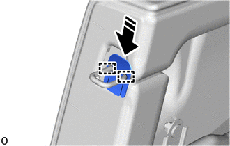
|
|
Install in this Direction |
Attach the guide and install the seatback cover plate RH as shown in the illustration.
15.INSTALL SEAT COVER WIRE
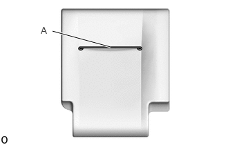
Install the seat cover wire.
- HINT:
- ·
Wire 1000 mm (3.28 ft.) or longer and shaped wire are available as supplied parts.
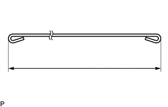
·For wire 1000 mm (3.28 ft.) or less in length, cut or shape 1000 mm (3.28 ft.) wire into the dimensions shown in the illustration.
·Make sure to read the Precaution section before preparing the wire.
Click hereVehicle Interior>SEAT>FRONT SEAT ASSEMBLY (for Separate Seat Type)>PRECAUTION
- Dimensions:
A 250 mm (9.84 in.)
- HINT:
-
-
The dimensions shown in the illustration are the length.
71073A
16.INSTALL FRONT SEATBACK COVER SUB-ASSEMBLY RH
- HINT:
-
When installing a front seatback cover sub-assembly RH, refer to the Precaution section in order to prevent wrinkles from forming.
-
Click hereVehicle Interior>SEAT>FRONT SEAT ASSEMBLY (for Separate Seat Type)>PRECAUTION
w/ Front Seat Side Airbag:
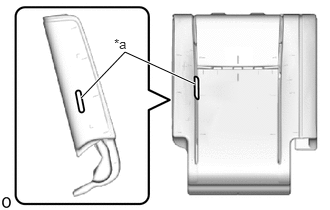
| *a | Hole |
Pass the bracket of the front seatback cover sub-assembly RH through the hole of the front seatback pad RH.
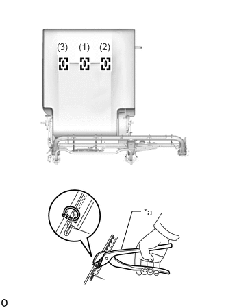
| *a | Hog Ring Pliers |
Using hog ring pliers, install the front seatback cover sub-assembly RH with 3 new hog rings in the order indicated in the illustration.
- NOTICE:
- ·
Be careful not to dirty or damage the front seatback cover sub-assembly RH.
- ·
Be sure to securely install the hog rings as shown in the illustration while preventing wrinkles from forming on the front seatback cover sub-assembly RH.
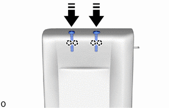
|
|
Install in this Direction |
Attach the claw and install the 2 front seat headrest support assemblies as shown in the illustration.
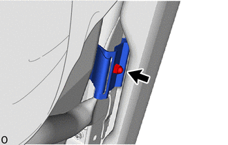
w/ Front Seat Side Airbag:
Install the bracket of the front seatback cover sub-assembly RH with a new nut.
- Torque:
- 12.5 N*m (127 kgf*cm, 9 ft.*lbf)
- CAUTION:
-
Do not reuse the nut.
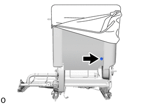
Install the clip.
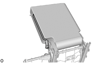
Close the fastener.
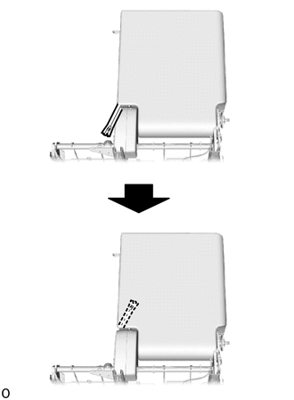
Insert the fastener.
Attach the hook.
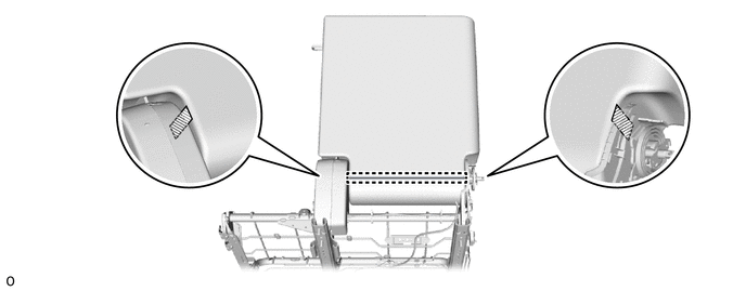

|
Fastening Tape | - | - |
Attach the fastening tape.
73178A
17.INSTALL SEAT BELT ANCHOR COVER CAP
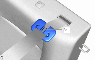
| *a | Slit |
Pass the front seat 3 point type belt assembly LH through the slit of rear seat shoulder belt cover.
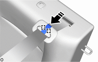
|
|
Install in this Direction |
Attach the guide and install the seat belt anchor cover cap as shown in the illustration.
73373
18.INSTALL REAR SEAT SHOULDER BELT COVER
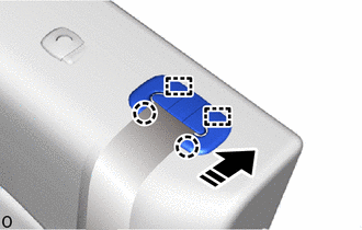
|
|
Install in this Direction |
Attach the guide and claw and install the rear seat shoulder belt cover as shown in the illustration.
78970G
19.INSTALL FRONT SEATBACK LOCK BAND ASSEMBLY RH
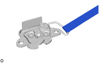
Install the front seatback lock band assembly RH.
72510H
20.INSTALL FRONT SEATBACK LOCK ASSEMBLY RH
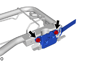
Install the front seatback lock assembly RH with the 2 bolts.
- Torque:
- 21 N*m (214 kgf*cm, 15 ft.*lbf)
71095
21.INSTALL CENTER SEATBACK COVER SUB-ASSEMBLY
Install the center seatback cover sub-assembly.
22.INSTALL CENTER SEATBACK COVER WITH PAD
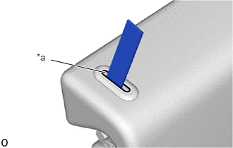
| *a | Hole |
Pass the front seatback lock band assembly RH through the hole of the center seatback cover with pad.
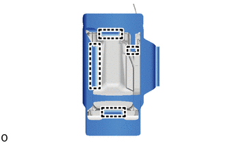
Attach the hook.
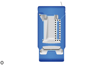
Attach the hook and install the center seatback cover with pad.
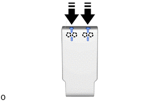
|
|
Install in this Direction |
Attach the claw and install the 2 front center seat headrest support assemblies as shown in the illustration.
71705H
23.INSTALL FRONT CENTER SEATBACK BOARD SUB-ASSEMBLY RH
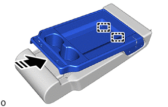
|
|
Install in this Direction |
Attach the guide as shown in the illustration.
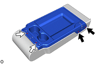

|
Clip |

|
Screw |
Install the 2 clips.
Install the front center seatback board sub-assembly RH with the 2 screws.
71784A
24.INSTALL FRONT SEATBACK BOARD CAP
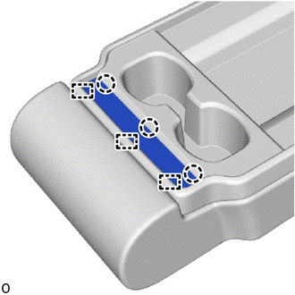
Attach the claw and guide and install the front seatback board cap.
72521
25.INSTALL LOWER RECLINING ADJUSTER ARM RH
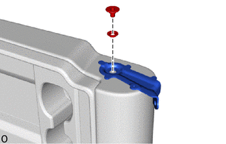
Using a T45 "TORX" socket wrench, install the lower reclining adjuster arm RH with the front seat reclining spacer RH and "TORX" screw.
- Torque:
- 21 N*m (214 kgf*cm, 15 ft.*lbf)
71397F
26.INSTALL CENTER SEAT UPPER HINGE COVER RH
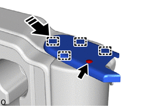
|
|
Install in this Direction |
Attach the guide as shown in the illustration.
Install the center seat upper hinge cover RH with the clip.
71811U
27.INSTALL BENCH TYPE FRONT SEAT CUSHION SHIELD
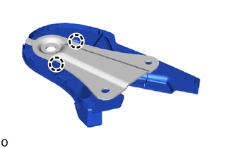
Attach the claw and install the bench type front seat cushion shield.
71387A
28.INSTALL CENTER SEAT LOWER HINGE ARM RH
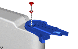
Using a T45 "TORX" socket wrench, install the center seat lower hinge arm RH with the front seat reclining spacer LH and "TORX" screw.
- Torque:
- 21 N*m (214 kgf*cm, 15 ft.*lbf)
29.INSTALL CENTER SEATBACK ASSEMBLY
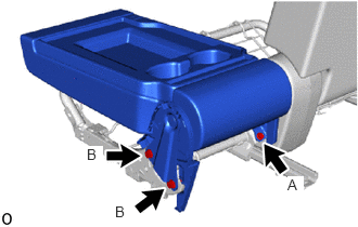
Temporalily install the center seatback assembly with the 3 bolts.
Tighten the 3 bolts.
- Torque:
- Bolt A : 21 N*m (214 kgf*cm, 15 ft.*lbf)
- Bolt B : 42 N*m (428 kgf*cm, 31 ft.*lbf)
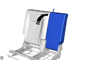
|
|
Lift in this Direction |
Lift up the center seatback assembly as shown in the illustration.
30.INSTALL SEAT COVER WIRE
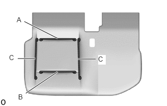
Install the seat cover wire.
- HINT:
- ·
Wire 1000 mm (3.28 ft.) or longer and shaped wire are available as supplied parts.
·For wire 1000 mm (3.28 ft.) or less in length, cut or shape 1000 mm (3.28 ft.) wire into the dimensions shown in the illustration.
·Make sure to read the Precaution section before preparing the wire.
Click hereVehicle Interior>SEAT>FRONT SEAT ASSEMBLY (for Separate Seat Type)>PRECAUTION
- Dimensions:
A 280 mm (11.02 in.) B 300 mm (11.8 in.) C 350 mm (1.15 ft.)
- HINT:
-
-
The dimensions shown in the illustration are the length.
71071
31.INSTALL FRONT SEAT CUSHION COVER SUB-ASSEMBLY RH
- HINT:
-
When installing a front seat cushion cover sub-assembly RH, refer to the Precaution section in order to prevent wrinkles from forming.
-
Click hereVehicle Interior>SEAT>FRONT SEAT ASSEMBLY (for Separate Seat Type)>PRECAUTION
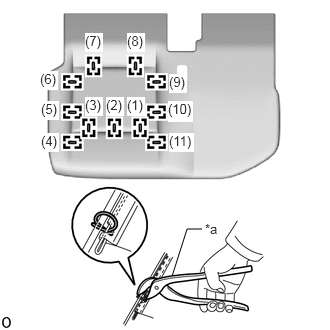
| *a | Hog Ring Pliers |
Using hog ring pliers, install the front seat cushion cover sub-assembly RH with 11 new hog rings in the order indicated in the illustration.
- NOTICE:
- ·
Be careful not to dirty or damage the front seat cushion cover sub-assembly RH.
- ·
Be sure to securely install the hog rings as shown in the illustration while preventing wrinkles from forming on the front seat cushion cover sub-assembly RH.
32.INSTALL FRONT SEAT CUSHION COVER WITH PAD
Set the front seat cushion cover with pad.
w/ Seat Belt Warning System:
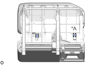
| *A | w/ Center Seat Occupant Detection Sensor |
Attach the clamp.
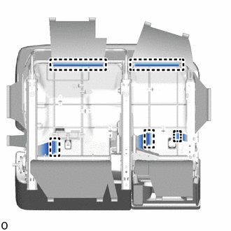
Attach the hook and install the front seat cushion cover with pad.
73240
33.INSTALL FRONT SEAT INNER BELT ASSEMBLY RH
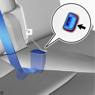
| *a | Hole |
|
|
Band |
Pass the front seat inner belt assembly RH and seat anchor of the front seat 3 point type belt assembly LH through the hole of the front seat cushion assembly.
Attach the band.
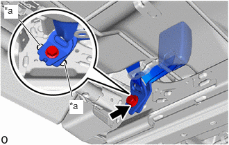
| *a | Protruding Part |
Install the front seat inner belt assembly RH and seat anchor of the front seat 3 point type belt assembly LH with the bolt.
- Torque:
- 42 N*m (428 kgf*cm, 31 ft.*lbf)
- NOTICE:
-
Do not allow the anchor part of the front seat inner belt assembly RH to overlap the protruding part.
w/ Seat Belt Warning System:
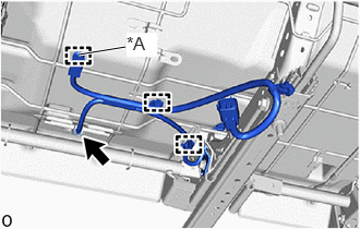
| *A | w/ Center Seat Occupant Detection Sensor |
Attach the clamp.
Connect the connector.
73250
34.INSTALL FRONT CENTER SEAT BELT ASSEMBLY
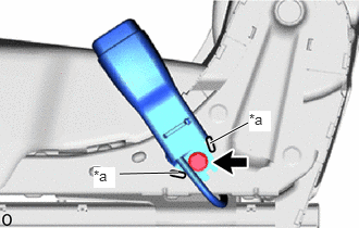
| *a | Protruding Part |
Install the front center seat belt assembly with the bolt.
- Torque:
- 42 N*m (428 kgf*cm, 31 ft.*lbf)
- NOTICE:
-
Do not allow the anchor part of the front seat inner belt assembly RH to overlap the protruding part.
w/ Center Seat Occupant Detection Sensor:
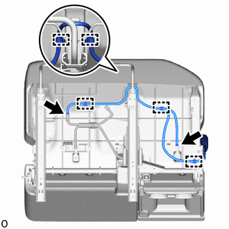
Attach the clamp.
Connect the 2 connectors.
Attach the hook.
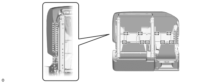
71811T
35.INSTALL FRONT SEAT CUSHION SHIELD RH
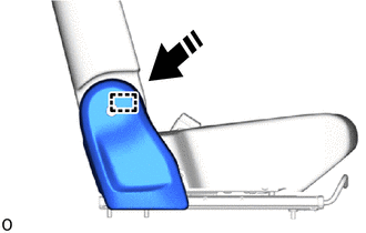
|
|
Install in this Direction |
Attach the guide as shown in the illustration.
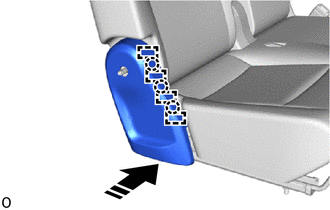
|
|
Install in this Direction |
Attach the claw and guide as shown in the illustration.
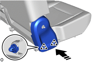
|
|
Install in this Direction |
Attach the claw as shown in the illustration.
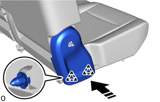
|
|
Install in this Direction |
Attach the clip and install the front seat cushion shield RH as shown in the illustration.
71396K
36.INSTALL CENTER SEAT HINGE COVER LH
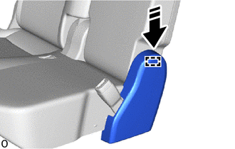
|
|
Install in this Direction |
Attach the guide as shown in the illustration.
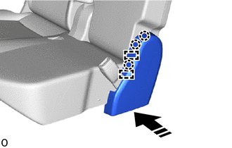
|
|
Install in this Direction |
Attach the guide and claw as shown in the illustration.
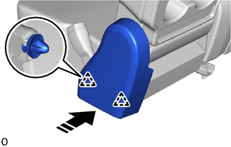
|
|
Install in this Direction |
Attach the clip as shown in the illustration.
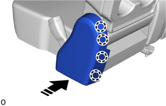
|
|
Install in this Direction |
Attach the claw and install the center seat hinge cover LH as shown in the illustration.
72525M
37.INSTALL RECLINING ADJUSTER RELEASE HANDLE RH
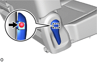
Attach the guide.
Install the reclining adjuster release handle RH with the screw.
72329D
38.INSTALL SEAT ADJUSTER BOLT COVER RH
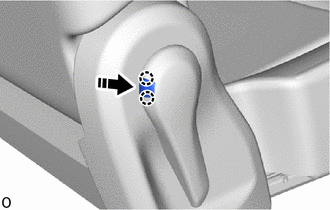
|
|
Install in this Direction |
Attach the claw and install the seat adjuster bolt cover RH as shown in the illustration.
71130B
39.INSTALL FRONT SEAT LEG ASSEMBLY RH
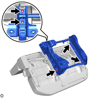
Install the front seat leg assembly RH with the 5 nuts.
- Torque:
- 21 N*m (214 kgf*cm, 15 ft.*lbf)
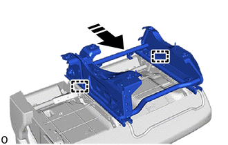
|
|
Slide in this Direction |
Operate the seat track adjusting handle RH and move the front seat assembly RH to the rearmost position and attach the guide.
w/ Front Seat Side Airbag:
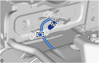
Attach the clamp and claw.
w/ Seat Belt Warning System:
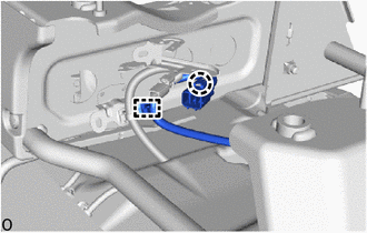
Attach the clamp and claw.
71139N
40.INSTALL FRONT SEAT INNER LEG COVER RH
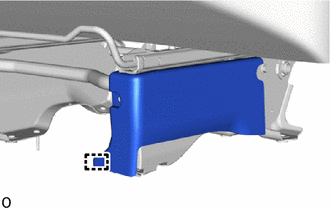
Attach the guide.
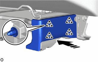
|
|
Install in this Direction |
Attach the clip as shown in the illustration.
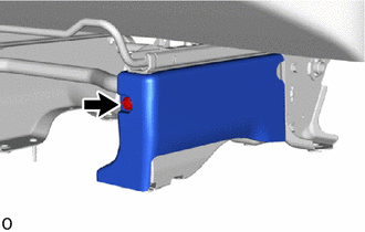
Install the front seat inner leg cover RH with the clip.
72345L
41.INSTALL RECLINING CONNECTING PIPE RH
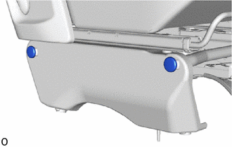
Install the 2 reclining connecting pipes RH.
71848N
42.INSTALL FRONT SEAT NO. 1 ADJUSTER COVER CAP RH
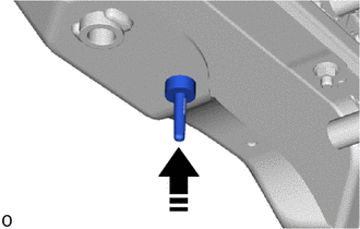
|
|
Install in this Direction |
Install the front seat No. 1 adjuster cover cap RH as shown in the illustration.
71848P
43.INSTALL FRONT SEAT NO. 2 ADJUSTER COVER CAP RH
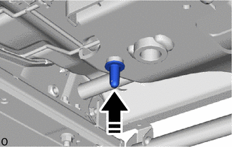
|
|
Install in this Direction |
Install the front seat No. 2 adjuster cover cap RH as shown in the illustration.