1GD-FTV INTAKE / EXHAUST INTERCOOLER INSTALLATION
PROCEDURE

 1.INSTALL GROMMET
Install the 2 grommets to the lower radiator support assembly.
17940D
2.INSTALL INTERCOOLER ASSEMBLY
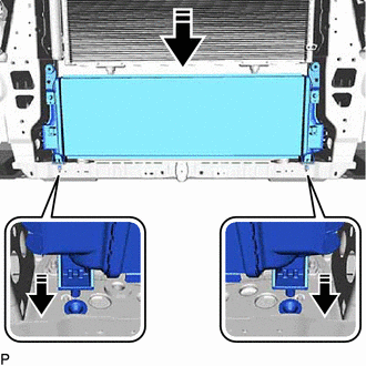
Attach the 2 grommets and connect the 2 guides to intercooler assembly.
88689E
3.INSTALL NO. 1 COOLER BRACKET
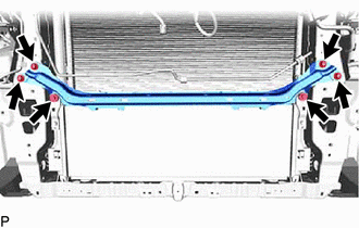
Install the No. 1 cooler bracket to the radiator support assembly with the 4 nuts.
- Torque:
- 24 N*m (245 kgf*cm, 18 ft.*lbf)
Install the intercooler assembly to the No. 1 cooler bracket with the 2 bolts.
- Torque:
- 6.0 N*m (61 kgf*cm, 53 in.*lbf)
17942
4.INSTALL NO. 2 INTERCOOLER AIR GUIDE
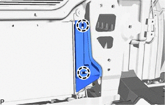
Attach the claws to install the No. 2 intercooler air guide.
17941
5.INSTALL NO. 1 INTERCOOLER AIR GUIDE
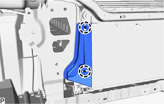
Attach the claws to install the No. 1 intercooler air guide.
17312B
6.INSTALL NO. 2 AIR INLET DUCT
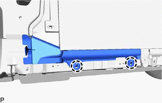
for RH Side:
Attach the claws to install the No. 2 air inlet duct.
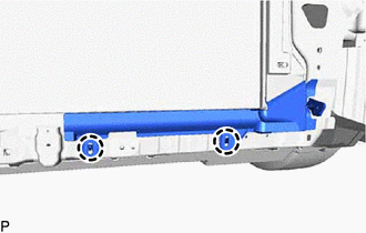
for LH Side:
Attach the claws to install the No. 2 air inlet duct.
44402
7.CONNECT NO. 1 POWER STEERING OIL COOLER SUB-ASSEMBLY
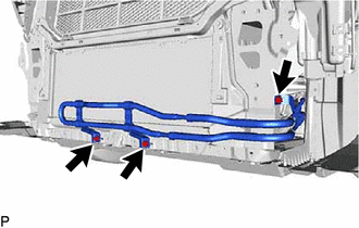
for LHD:
Connect the No. 1 power steering oil cooler sub-assembly with the 3 bolts.
- Torque:
- 28 N*m (286 kgf*cm, 21 ft.*lbf)
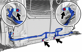
for RHD:
Connect the No. 1 power steering oil cooler sub-assembly with the 4 bolts.
- Torque:
- 28 N*m (286 kgf*cm, 21 ft.*lbf)
53287B
8.INSTALL RADIATOR SUPPORT EXTENSION RH
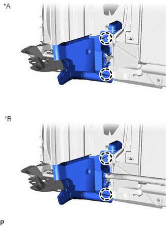
| *A | for LHD |
| *B | for RHD |
Attach the claws to install the radiator support extension RH.
53288B
9.INSTALL RADIATOR SUPPORT EXTENSION LH
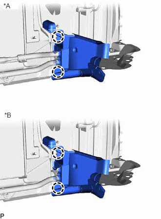
| *A | for LHD |
| *B | for RHD |
Attach the claws to install the radiator support extension LH.
17303T
10.INSTALL AIR PIPE SUB-ASSEMBLY
- NOTICE:
- ·
When tightening the hose clamp, carefully tighten it so that it does not become damaged.
·The tightening method for the hose clamp differs depending on the shape of the air pipe sub-assembly.
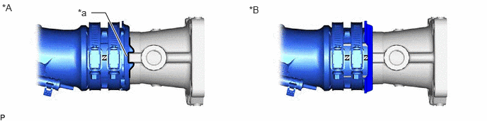 1.865,0.833 1.552,0.188 1.552,0.188 1.344,0.188 true 0.031,0.031 0.344,0.188 0.313,0.156 10 false *A 3.667,0.063 3.979,0.219 0.313,0.156 10 false *B 1.146,0.104 1.458,0.26 0.313,0.156 10 false *a
*A for Type A *B for Type B *a Cutout - -
Intake Air Connector Side (for Type A):
Install 2 new hose clamps to the air pipe sub-assembly.
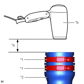
| *1 | Hose Clamp |
| *2 | Air Pipe Sub-assembly |
| *a | 50 mm (1.97 in.) or Less |
| *b | Hair Dryer |
When the ambient temperature drops below 15°C: [*1]
Using a hair dryer, warm the inside of the air pipe sub-assembly as shown in the illustration.
- Recommended Hair Dryer Rated Power:
1200 W
- HINT:
- ·
Warm the part until the temperature is 30°C or more.
·Warm the part for 90 seconds or more.
·After warming, connect the air pipe sub-assembly within 5 minutes and tighten the hose clamp.
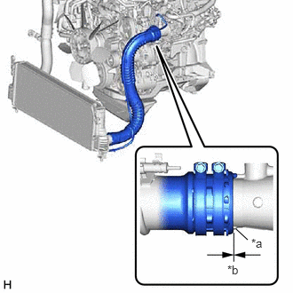
| *a | Stopper |
| *b | 0 to 3 mm (0 to 0.118 in.) |
Connect the air pipe sub-assembly to the intake air connector.
- HINT:
-
Make sure the hose clamp is oriented as shown in the illustration.
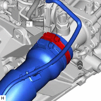
| *1 | Hose Clamp (A) |
Tighten the hose clamp (A).
- NOTICE:
-
Do not use electric or pneumatic tools.
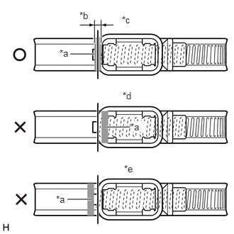
| *a | Paint Mark |
| *b | 2.0 mm (0.0787 in.) |
| *c | CORRECT |
| *d | INCORRECT (1) |
| *e | INCORRECT (2) |
Make sure that the paint mark of the hose clamp (A) is positioned as shown in the illustration.
- NOTICE:
- When "INCORRECT (1)":·
Disconnect the air pipe sub-assembly and replace the hose clamp (A) with new ones.
·Perform the procedure again from [*1].
- NOTICE:
- When "INCORRECT (2)":·
With the air pipe sub-assembly connected, warm the air pipe sub-assembly from the outside. (When the ambient temperature drops below 15°C.)
- HINT:
- ·
Warm the part until the temperature is 30°C or more.
·Warm the part for 90 seconds or more.
·Tighten the hose clamp (A) and check the position of the paint mark of the hose clamp (A) again.
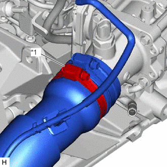
| *1 | Hose Clamp (B) |
Tighten the hose clamp (B).
- NOTICE:
-
Do not use electric or pneumatic tools.
| *a | Paint Mark |
| *b | 2.0 mm (0.0787 in.) |
| *c | CORRECT |
| *d | INCORRECT (1) |
| *e | INCORRECT (2) |
Make sure that the paint mark of the hose clamp (B) is positioned as shown in the illustration.
- NOTICE:
- When "INCORRECT (1)":·
Disconnect the air pipe sub-assembly and replace the hose clamps (A and B) with new ones.
·Perform the procedure again from [*1].
- NOTICE:
- When "INCORRECT (2)":·
With the air pipe sub-assembly connected, warm the air pipe sub-assembly from the outside. (When the ambient temperature drops below 15°C.)
- HINT:
- ·
Warm the part until the temperature is 30°C or more.
·Warm the part for 90 seconds or more.
·Tighten the hose clamp (B) and check the position of the paint mark of the hose clamp (B) again.
Intake Air Connector Side (for Type B):
Install 2 new hose clamps to the air pipe sub-assembly.
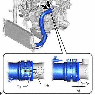
| *a | Paint Mark |
| *b | Rib |
| *c | Stopper |
| *d | 0 to 3 mm (0 to 0.118 in.) |
Connect the air pipe sub-assembly to the intake air connector with 2 new hose clamps as shown in the illustration.
- Torque:
- 9.5 N*m (97 kgf*cm, 84 in.*lbf)
- NOTICE:
- ·
Do not reuse the hose clamp.
·Tighten the hose clamps in the order shown in the illustration.
- HINT:
-
Make sure the hose clamp is oriented as shown in the illustration.
Intercooler Assembly Side:
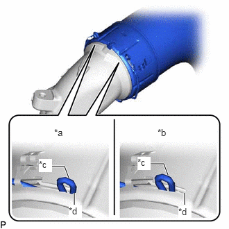
| *a | Correct |
| *b | Incorrect |
| *c | Retainer End |
| *d | Stopper |
Connect the No. 2 air tube to the intercooler assembly and lock the retainer.
- NOTICE:
-
Securely insert the retainer so that the 4 locks are engaged. Then, pull and check that the locks are engaged and that the hose cannot be pulled out.
- HINT:
-
Make sure that the retainer end contacts the stopper as shown in the illustration.
25761B
11.CONNECT NO. 1 VACUUM TRANSMITTING HOSE
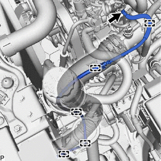
for Diesel Throttle Body Side:
Attach the 5 clamps and connect the No. 1 vacuum transmitting hose to the intercooler assembly, and slide the clip to secure the hose to the engine oil dipstick guide.
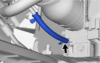
for Intercooler Assembly Side:
Connect the No. 1 vacuum transmitting hose to the intercooler assembly, and slide the clip to secure the hose.
17030
12.INSTALL AIR HOSE ASSEMBLY
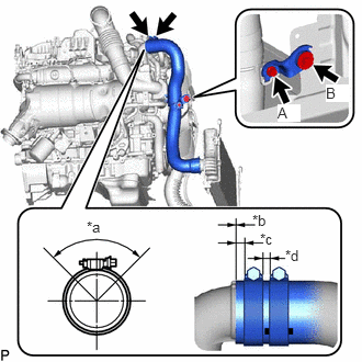
| *a | 90° |
| *b | 0 to 3 mm (0 to 0.118 in.) |
| *c | 2 to 7 mm (0.0787 to 0.276 in.) |
| *d | No Contact Hose Clamps |
Connect the air hose assembly to the turbine outlet elbow with 2 new hose clamps as shown in the illustration.
- Torque:
- 9.5 N*m (97 kgf*cm, 84 in.*lbf)
- NOTICE:
-
Do not reuse the hose clamp.
- HINT:
-
Make sure the hose clamp is oriented as shown in the illustration.
Install the air tube support bracket with 2 bolts to the air hose assembly and radiator support.
- Torque:
- for bolt A : 8.0 N*m (82 kgf*cm, 71 in.*lbf)
- for bolt B : 6.0 N*m (61 kgf*cm, 53 in.*lbf)
Connect the air hose assembly to the intercooler assembly and lock the retainer.
- NOTICE:
-
Securely insert the retainer so that the 4 locks are engaged. Then, pull and check that the locks are engaged and that the hose cannot be pulled out.
- HINT:
-
1.031,2.667 0.969,2.5 0.969,2.5 0.771,2.5 true 2.521,2.625 2.458,2.458 2.458,2.458 2.26,2.458 true 1.115,3.073 1.115,2.896 true 2.771,3.073 2.771,2.896 true 0.813,1.906 1.125,2.063 0.313,0.156 10 false *a 2.365,1.906 2.677,2.063 0.313,0.156 10 false *b 0.583,2.385 0.781,2.583 0.198,0.198 10 true *c 2.063,2.354 2.26,2.552 0.198,0.198 10 true *c 1.031,3.083 1.229,3.281 0.198,0.198 10 true *d 2.677,3.094 2.875,3.292 0.198,0.198 10 true *d
*a Correct *b Incorrect *c Retainer End *d Stopper
-
Make sure that the retainer end contacts the stopper as shown in the illustration.
16546
13.INSTALL RADIATOR PROTECTOR (w/o Air Conditioning System)
53209B
14.INSTALL HOOD LOCK SUPPORT BRACE SUB-ASSEMBLY
53510
15.INSTALL HOOD LOCK ASSEMBLY
88590D
16.INSTALL BLOWER ASSEMBLY WITH SHROUD (w/ Condenser Fan)
for LH Side:
Click hereVehicle Interior>HEATING / AIR CONDITIONING>CONDENSER FAN>INSTALLATION
for LH Side:
Click hereVehicle Interior>HEATING / AIR CONDITIONING>CONDENSER FAN>INSTALLATION
86510
17.INSTALL HIGH PITCHED HORN ASSEMBLY (for 2-piece Type)
Click hereVehicle Exterior>HORN>HORN>INSTALLATION
86520
18.INSTALL LOW PITCHED HORN ASSEMBLY
Click hereVehicle Exterior>HORN>HORN>INSTALLATION
52021
19.INSTALL FRONT BUMPER REINFORCEMENT SUB-ASSEMBLY