7GR-FKS INTAKE / EXHAUST EXHAUST MANIFOLD REMOVAL
CAUTION / NOTICE / HINT
The necessary procedures (adjustment, calibration, initialization or registration) that must be performed after parts are removed and installed, or replaced during exhaust manifold removal/installation are shown below.
| Replaced Part or Performed Procedure | Necessary Procedure | Effect/Inoperative Function when Necessary Procedure not Performed | Link |
|---|---|---|---|
·
Replacement of air fuel ratio sensor ·
Gas leak from exhaust system is repaired |
Inspection After Repair | ·
Poor idle, etc. ·
Engine start function, etc. |
( ) |
- CAUTION:
- ·
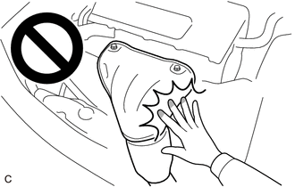
To prevent burns, do not touch the engine, exhaust manifold or other high temperature components while the engine is hot.
·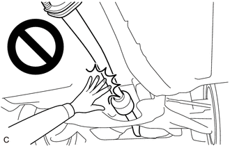
To prevent burns, do not touch the engine, exhaust pipe or other high temperature components while the engine is hot.
PROCEDURE

 51406A
1.REMOVE NO. 2 ENGINE UNDER COVER SUB-ASSEMBLY (w/ No. 2 Engine Under Cover Sub-assembly)
52618
2.REMOVE LOWER FRONT BUMPER ABSORBER
51405A
3.REMOVE NO. 1 ENGINE UNDER COVER ASSEMBLY
17403
4.REMOVE FRONT NO. 3 EXHAUST PIPE SUB-ASSEMBLY
17410
5.REMOVE FRONT EXHAUST PIPE ASSEMBLY
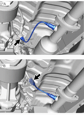
| *A | for Automatic Transmission |
| *B | for Manual Transmission |
w/ Secondary Air Injection System:
Disconnect the heated oxygen sensor connector.
w/o Secondary Air Injection System:
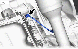
| *A | for Automatic Transmission |
Disconnect the heated oxygen sensor connector.
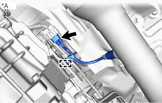
| *A | for Manual Transmission |
Disconnect the heated oxygen sensor connector and detach the wire harness clamp.
Remove the 2 nuts, 2 bolts and front exhaust pipe assembly.
Remove the 2 gaskets from the front exhaust pipe assembly.
17450B
6.REMOVE FRONT NO. 2 EXHAUST PIPE ASSEMBLY
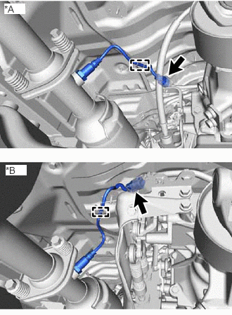
| *A | for Automatic Transmission |
| *B | for Manual Transmission |
w/ Secondary Air Injection System:
Disconnect the heated oxygen sensor connector and detach the wire harness clamp.
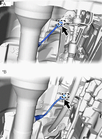
| *A | for Automatic Transmission |
| *B | for Manual Transmission |
w/o Secondary Air Injection System:
Disconnect the heated oxygen sensor connector and detach the wire harness clamp.
Remove the 2 nuts, 2 bolts, 2 compression springs and exhaust pipe support and front No. 2 exhaust pipe assembly.
Remove the 2 gaskets from the front No. 2 exhaust pipe assembly.
17118
7.REMOVE MANIFOLD STAY
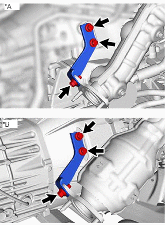
| *A | w/ Secondary Air Injection System |
| *B | w/o Secondary Air Injection System |
Remove the 3 bolts and manifold stay from the transmission assembly and exhaust manifold assembly RH.
11409
8.REMOVE ENGINE OIL LEVEL DIPSTICK GUIDE (w/ Secondary Air Injection System)
17361N
9.REMOVE NO. 1 AIR TUBE (w/ Secondary Air Injection System)

|
Bolt |

|
Nut |
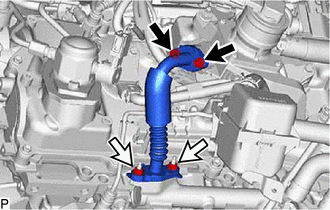
Remove the 2 bolts, 2 nuts and No. 1 air tube from the No. 1 emission control valve set and exhaust manifold assembly RH.
Remove the 2 gaskets from the No. 1 air tube.
- NOTICE:
-
Be careful not to damage the installation surfaces of the gaskets.
17140
10.REMOVE EXHAUST MANIFOLD ASSEMBLY RH
w/o Secondary Air Injection System:
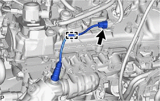
Disconnect the air fuel ratio sensor connector and detach the wire harness clamp.
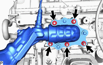
Remove the 5 nuts, exhaust manifold assembly RH and gasket from the cylinder head sub-assembly.
w/ Secondary Air Injection System:
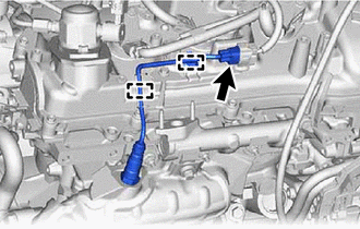
Disconnect the air fuel ratio sensor connector and detach the 2 wire harness clamps.
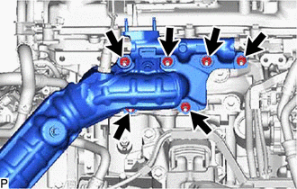
Remove the 6 nuts, exhaust manifold assembly RH and gasket from the cylinder head sub-assembly.
89467B
11.REMOVE AIR FUEL RATIO SENSOR (for Bank 1 Sensor 1)
17119
12.REMOVE NO. 2 MANIFOLD STAY
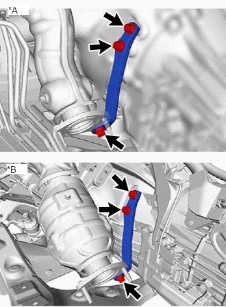
| *A | w/ Secondary Air Injection System |
| *B | w/o Secondary Air Injection System |
Remove the 3 bolts and No. 2 manifold stay from the transmission assembly and exhaust manifold assembly LH.
17362
13.REMOVE NO. 2 AIR TUBE (w/ Secondary Air Injection System)
|
|
Bolt |
|
|
Nut |
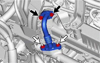
Remove the 2 bolts, 2 nuts and No. 2 air tube from the No. 2 emission control valve set and exhaust manifold assembly LH.
Remove the 2 gaskets from the No. 2 air tube.
- NOTICE:
-
Be careful not to damage the installation surfaces of the gaskets.
17150
14.REMOVE EXHAUST MANIFOLD ASSEMBLY LH
w/o Secondary Air Injection System:
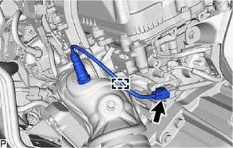
Disconnect the air fuel ratio sensor connector and detach the wire harness clamp.
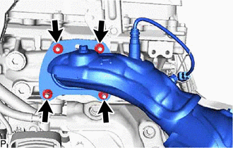
Remove the 4 nuts, exhaust manifold assembly LH and gasket from the cylinder head LH.
w/ Secondary Air Injection System:
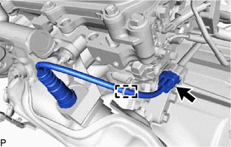
Disconnect the air fuel ratio sensor connector and detach the wire harness clamp.
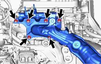
Remove the 6 nuts, exhaust manifold assembly LH and gasket from the cylinder head LH.
89467B
15.REMOVE AIR FUEL RATIO SENSOR (for Bank 2 Sensor 1)
17168
16.REMOVE NO. 2 EXHAUST MANIFOLD HEAT INSULATOR (w/o Secondary Air Injection System)
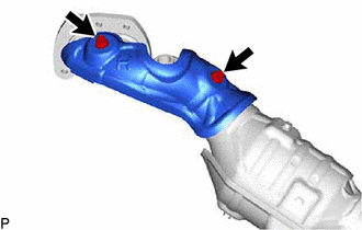
Remove the 2 bolts and No. 2 exhaust manifold heat insulator from the exhaust manifold assembly LH.