STEERING GEAR / LINKAGE STEERING GEAR(for LHD) REMOVAL
PROCEDURE

 1.PLACE FRONT WHEELS FACING STRAIGHT AHEAD
2.SECURE STEERING WHEEL ASSEMBLY
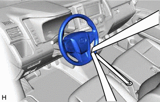
Secure the steering wheel assembly with the seat belt in order to prevent rotation.
- HINT:
-
This operation is useful to prevent damage to the spiral cable sub-assembly.
3.REMOVE FRONT WHEELS
51406A
4.REMOVE NO. 2 ENGINE UNDER COVER SUB-ASSEMBLY (w/ No. 2 Engine Under Cover Sub-assembly)
for 7GR-FKS: Click hereEngine / Hybrid System>7GR-FKS (ENGINE MECHANICAL)>ENGINE ASSEMBLY>REMOVAL
for 1GD-FTV: Click hereEngine / Hybrid System>1GD-FTV (ENGINE MECHANICAL)>ENGINE ASSEMBLY>REMOVAL
52618
5.REMOVE LOWER FRONT BUMPER ABSORBER
for 7GR-FKS: Click hereEngine / Hybrid System>7GR-FKS (ENGINE MECHANICAL)>ENGINE ASSEMBLY>REMOVAL
for 1GD-FTV: Click hereEngine / Hybrid System>1GD-FTV (ENGINE MECHANICAL)>ENGINE ASSEMBLY>REMOVAL
51405A
6.REMOVE NO. 1 ENGINE UNDER COVER SUB-ASSEMBLY
for 7GR-FKS: Click hereEngine / Hybrid System>7GR-FKS (ENGINE MECHANICAL)>ENGINE ASSEMBLY>REMOVAL
for 1GD-FTV: Click hereEngine / Hybrid System>1GD-FTV (ENGINE MECHANICAL)>ENGINE ASSEMBLY>REMOVAL
51108C
7.REMOVE REAR SIDE RAIL REINFORCEMENT SUB-ASSEMBLY
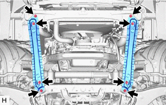
Remove the 8 bolts and 2 rear side rail reinforcement sub-assembly.
45047
8.DISCONNECT TIE ROD END SUB-ASSEMBLY LH
Remove the cotter pin and nut.
Install 2 spacers (09961-02080) to the steering knuckle LH as shown in the illustration.
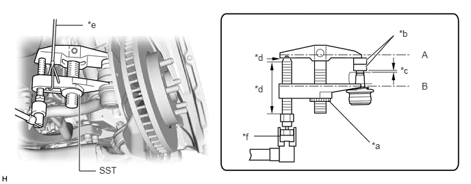
| *a | Center Nut | *b | SST (09961-02080) |
| *c | 1 mm (0.0394 in.) | *d | Molybdenum grease application area |
| *e | String | *f | Place wrench here |
- SST
- 09960-20010 09961-02080
- NOTICE:
-
Make sure that the clearance between the tie rod assembly LH and spacers (09961-02080) is 1 mm (0.0394 in.) or more to prevent damage to SST.
Using SST, separate the tie rod assembly LH from steering knuckle LH.
- SST
- 09960-20010 (09961-02010)
- CAUTION:
-
Apply molybdenum grease to the bolt threads and the tip of SST.
- NOTICE:
- ·
Be sure to tighten the string firmly to secure SST to the steering knuckle to prevent SST from falling off.
·Install SST so that (A) and (B) shown in the illustration are parallel. Otherwise, the ball joint dust cover may be damaged.
·Be sure to place the wrench on the part shown in the illustration.
·Do not damage the ball joint dust cover.
·Do not damage the steering knuckle.
·Do not damage the front disc brake dust cover.
45046
9.DISCONNECT TIE ROD END SUB-ASSEMBLY RH
- HINT:
-
Use the same procedure described for the LH side.
10.DISCONNECT INTERMEDIATE SHAFT ASSEMBLY
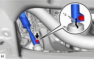
| *a | Matchmark |
Put matchmarks on the intermediate shaft assembly and rack and pinion power steering gear assembly.
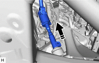

|
Install in this Direction |
Remove the bolt and intermediate shaft assembly from the rack and pinion power steering gear assembly.
44250
11.REMOVE RACK AND PINION POWER STEERING GEAR ASSEMBLY
for 1GD-FTV:
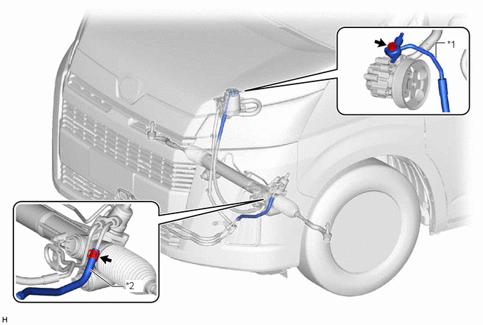
| *1 | Pressure Feed Tube | *2 | Return Hose |
Slide the clip and disconnect the return hose.
Remove the union bolt and disconnect the pressure feed tube.
Remove the gasket.
for 7GR-FKS:
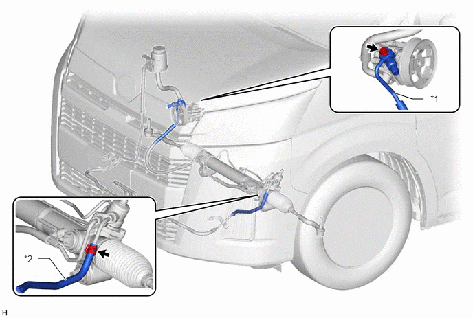
| *1 | Pressure Feed Tube | *2 | Return Hose |
Slide the clip and disconnect the return hose.
Remove the union bolt and disconnect the pressure feed tube.
Remove the gasket.
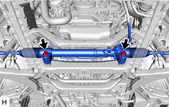
Remove the 2 bolts and rack and pinion power steering gear assembly from the front suspension member.