TELEMATICS TELEPHONE ANTENNA REMOVAL
CAUTION / NOTICE / HINT
The necessary procedures (adjustment, calibration, initialization or registration) that must be performed after parts are removed, installed or replaced during the No. 2 amplifier antenna assembly removal/installation are shown below.
| Replacement Part or Procedure | Necessary Procedures | Effect/Inoperative Function When Necessary Procedures are not Performed | Link |
|---|---|---|---|
| Disconnect cable from negative (-) battery terminal | Memorize steering angle neutral point | Parking assist monitor system | ( ) |
| Panoramic view monitor system | ()
|
- HINT:
-
When the cable is disconnected/reconnected to the battery terminal, systems temporarily stop operating. However, each system has a function that completes learning the first time the systems is used.
- ·
Learning completes when vehicle is driven
Effect/Inoperative Function When Necessary Procedures are not Performed Necessary Procedures Link Lane control system Drive the vehicle straight ahead at 15 km/h (10 mph) or more for 1 second or more. ( )
Pre-collision system
·Learning completes when vehicle is operated normally
Effect/Inoperative Function When Necessary Procedures are not Performed Necessary Procedures Link Power slide door system Fully close the slide door by hand.
- HINT:
-
Initialization is not necessary if the above procedures are performed while the slide door is closed.
( )
Air conditioning system After the ignition switch is turned to ON, the servo motor standard position is recognized. -
PROCEDURE

 1. PRECAUTION
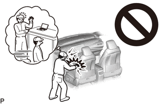
- CAUTION:
-
-
Be sure to read Precaution thoroughly before servicing.
- ·
for Type A:
Click hereVehicle Interior>SUPPLEMENTAL RESTRAINT SYSTEMS>AIRBAG SYSTEM (for Type A)>PRECAUTION
·for Type B:
Click hereVehicle Interior>SUPPLEMENTAL RESTRAINT SYSTEMS>AIRBAG SYSTEM (for Type B)>PRECAUTION
·for Type C:
Click hereVehicle Interior>SUPPLEMENTAL RESTRAINT SYSTEMS>AIRBAG SYSTEM (for Type C)>PRECAUTION
- NOTICE:
-
After turning the ignition switch off, waiting time may be required before disconnecting the cable from the negative (-) battery terminal.
-
Click hereGeneral>SETUP>WHEN DISCONNECTING OR RECONNECTING BATTERY TERMINAL>BEFORE DISCONNECTING BATTERY
2.DISCONNECT CABLE FROM NEGATIVE BATTERY TERMINAL
Click hereGeneral>MAINTENANCE>1GD-FTV BATTERY>REMOVAL
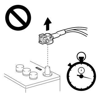
- CAUTION:
-
- ·
Wait at least 90 seconds after disconnecting the cable from the negative (-) battery terminal to disable the SRS system.
·If the airbag deploys for any reason, it may cause a serious accident.
3.REMOVE ROOF HEADLINING ASSEMBLY
for Standard Roof:
Click hereVehicle Interior>INTERIOR PANELS / TRIM>ROOF HEADLINING (for Wagon)>REMOVAL
for High Roof:
Click hereVehicle Interior>INTERIOR PANELS / TRIM>ROOF HEADLINING (for Semi-trim)>REMOVAL
4.REMOVE TIRE PRESSURE WARNING ECU WITH WINDSHIELD HEADER PANEL DAMPER SUB-ASSEMBLY RH (for Standard Roof)
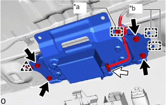
| *a | Clamp |
| *b | Guide |

|
Bolt |

|
Connector |
Disconnect the connector.
Detach the wire harness clamp.
Remove the 4 bolts.
Detach the clip and guide and remove the tire pressure warning ECU with windshield header panel damper sub-assembly RH.
86300C
5.REMOVE NO. 2 AMPLIFIER ANTENNA ASSEMBLY
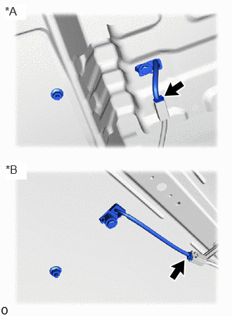
| *A | for Standard Roof |
| *B | for High Roof |
Disconnect the connector.
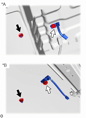
| *A | for Standard Roof |
| *B | for High Roof |
|
|
Nut |
|
|
Bolt |
Remove the nut and bolt.
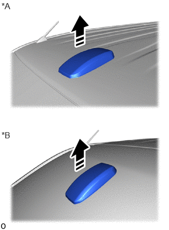
| *A | for Standard Roof |
| *B | for High Roof |

|
Remove in this Direction |
Remove the No. 2 amplifier antenna assembly as shown in the illustration.