WIPER / WASHER WIPER AND WASHER SYSTEM Headlight Cleaner Motor and Relay Circuit
DESCRIPTION
The headlight ECU sub-assembly RH controls the headlight cleaner motor and pump assembly.
WIRING DIAGRAM
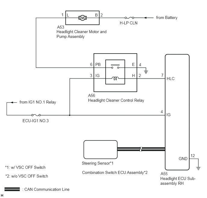
CAUTION / NOTICE / HINT
- NOTICE:
- ·
First check that the front washer operates normally.
Click hereVehicle Exterior>WIPER / WASHER>WIPER AND WASHER SYSTEM>OPERATION CHECK
·Check that the lighting system is normal before performing the following procedure.
·Inspect the fuses and relays for circuits related to this system before performing the following inspection procedure.
·If the headlight ECU sub-assembly LH has been replaced, it is necessary to synchronize the vehicle information and initialize the headlight ECU sub-assembly LH.
Click hereVehicle Exterior>LIGHTING (EXT)>LIGHTING SYSTEM (w/ Headlight ECU)>INITIALIZATION
·When replacing the headlight ECU sub-assembly LH, always replace it with a new one. If a headlight ECU sub-assembly LH which was installed to another vehicle is used, the information stored in it will not match the information from the vehicle and a DTC may be stored.
PROCEDURE
Connect the GTS to the DLC3.
Turn the ignition switch to ON.
Turn the GTS on.
Enter following menus: Body Electrical / HL AutoLeveling (Sub) / Active Test.
Perform the Active Test according to the display on the GTS.
- Body Electrical > HL AutoLeveling (Sub) > Active Test
-
Tester Display Measurement Item Control Range Diagnostic Note Headlight Cleaner Function to operate the headlight cleaner motor and pump assembly OFF or ON -
- Body Electrical > HL AutoLeveling (Sub) > Active Test
-
Tester Display Headlight Cleaner - 50004 414 1
- OK:
Headlight cleaner motor and pump assembly operate normally.
- Result:
Proceed to OK NG
OK
NG
Connect the GTS to the DLC3.
Turn the ignition switch to ON.
Turn the GTS on.
Enter following menus: Body Electrical / HL AutoLeveling (Sub) / Data List.
Read the Data List according to the display on the GTS.
- Body Electrical > HL AutoLeveling (Sub) > Data List
-
Tester Display Measurement Item Range Normal Condition Diagnostic Note Front Window Washer Switch Windshield wiper switch assembly (washer switch) condition OFF or ON OFF: Windshield wiper switch assembly (washer switch) off
ON: Windshield wiper switch assembly (washer switch) on-
- Body Electrical > HL AutoLeveling (Sub) > Data List
-
Tester Display Front Window Washer Switch - 50003 414 1
- OK:
On the GTS screen, ON or OFF is displayed accordingly.
- Result:
Result Proceed to OK A NG (w/ VSC switch) B NG (w/o VSC switch) C
A
B
C
Remove the headlight cleaner motor and pump assembly.
Click hereVehicle Exterior>WIPER / WASHER>HEADLIGHT CLEANER MOTOR>REMOVAL
Inspect the headlight cleaner motor and pump assembly.
Click hereVehicle Exterior>WIPER / WASHER>HEADLIGHT CLEANER MOTOR>ON-VEHICLE INSPECTION
- Result:
Proceed to OK NG
OK
NG
Remove the headlight cleaner control relay.
Click hereVehicle Exterior>WIPER / WASHER>HEADLIGHT CLEANER CONTROL RELAY>REMOVAL
Inspect the headlight cleaner control relay.
Click hereVehicle Exterior>WIPER / WASHER>RELAY>ON-VEHICLE INSPECTION
- Result:
Proceed to OK NG
OK
NG
Disconnect the A53 headlight cleaner motor and pump assembly connector.
Disconnect the A56 headlight cleaner control connector.
Measure the resistance according to the value(s) in the table below.
- Standard Resistance:
Tester Connection Condition Specified Condition A53-1 (L) - A56-6 (PB) Always Below 1 Ω A53-1 (L) or A56-6 (PB) - Body ground Always 10 kΩ or higher
Measure the voltage according to the value(s) in the table below.
- Standard Voltage:
Tester Connection Switch Condition Specified Condition A53-2 (B) - Body ground Ignition switch off 11 to 14 V
- Result:
Proceed to OK NG
OK
NG
Disconnect the A56 headlight cleaner control relay connector.
Disconnect the A55 headlight ECU sub-assembly RH connector.
Measure the resistance according to the value(s) in the table below.
- Standard Resistance:
Tester Connection Condition Specified Condition A56-2 (H) - A55-7 (HLC) Always Below 1 Ω A56-4 (E) - Body ground Always Below 1 Ω A56-2 (H) or A55-7 (HLC) - Body ground Always 10 kΩ or higher
Measure the voltage according to the value(s) in the table below.
- Standard Voltage:
Tester Connection Switch Condition Specified Condition A56-3 (IG) - Body ground Ignition switch off Below 1 V Ignition switch ON 11 to 14 V
- Result:
Proceed to OK NG
OK
NG