HEATING / AIR CONDITIONING CONDENSER FAN REMOVAL
CAUTION / NOTICE / HINT
The necessary procedures (adjustment, calibration, initialization, or registration) that must be performed after parts are replaced during the condenser fan removal/installation are shown below.
| Replaced Part or Performed Procedure | Necessary Procedures | Effect/Inoperative Function When Necessary Procedures are not Performed | Link |
|---|---|---|---|
·
Front television camera assembly (Including removal and installation) ·
Radiator grille assembly (Including removal and installation) ·
Front bumper assembly (Including removal and installation) |
Front television camera view adjustment | Panoramic view monitor system | ( ) |
·
Front television camera assembly, radiator grille assembly or front bumper assembly ·
Television camera assembly ·
Side television camera assembly LH or outer rear view mirror assembly LH ·
Side television camera assembly RH or outer rear view mirror assembly RH |
Television camera view adjustment (Adjustment of all cameras)
|
Panoramic view monitor system | ()
|
- HINT:
- ·
When the front bumper is damaged or deformed due to an accident or contact with other objects, etc., or the bumper installation area on the body is repaired, it is necessary to perform millimeter wave radar sensor adjustment.
Click hereEngine / Hybrid System>CRUISE CONTROL>MILLIMETER WAVE RADAR SENSOR>ADJUSTMENT
PROCEDURE

 1.REMOVE FRONT BUMPER ASSEMBLY
except Wagon:
Click hereVehicle Exterior>EXTERIOR PANELS / TRIM>FRONT BUMPER (except Wagon)>REMOVAL
for Wagon:
Click hereVehicle Exterior>EXTERIOR PANELS / TRIM>FRONT BUMPER (for Wagon)>REMOVAL
86510
2.REMOVE HIGH PITCHED HORN ASSEMBLY
Click hereVehicle Exterior>HORN>HORN>REMOVAL
86520
3.REMOVE LOW PITCHED HORN ASSEMBLY
Click hereVehicle Exterior>HORN>HORN>REMOVAL
17311B
4.REMOVE NO. 1 AIR INLET DUCT
53286F
5.REMOVE RADIATOR SIDE AIR SEAL LH
except Wagon:
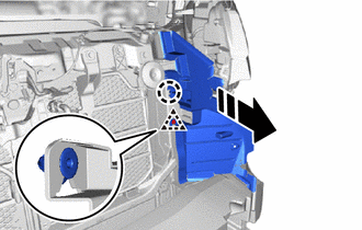

|
Remove in this Direction |
Detach the clip and claw to remove the radiator side air seal LH.
for Wagon:
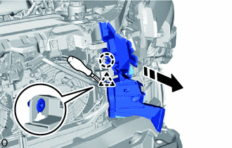
|
|
Remove in this Direction |
Detach the clip and claw to remove the radiator side air seal LH.
53285N
6.REMOVE RADIATOR SIDE AIR SEAL RH
except Wagon:
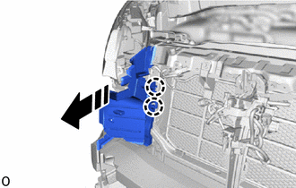
|
|
Remove in this Direction |
Detach the claw and remove the radiator side air seal RH.
for Wagon:
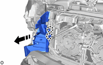
|
|
Remove in this Direction |
Detach the claw and remove the radiator side air seal RH.
51466
7.REMOVE UPPER RADIATOR SUPPORT BRACE LH (for Wagon)
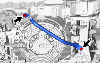
Remove the 2 bolts and upper radiator support brace LH.
51465
8.REMOVE UPPER RADIATOR SUPPORT BRACE RH (for Wagon)
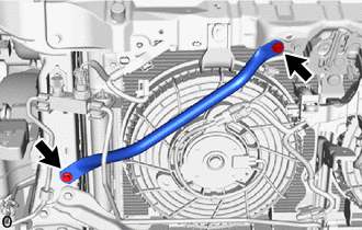
Remove the 2 bolts and upper radiator support brace RH.
53510
9.REMOVE HOOD LOCK ASSEMBLY (for LHD)
53510
10.REMOVE HOOD LOCK ASSEMBLY (for RHD)
88590E
11.REMOVE NO. 2 BLOWER ASSEMBLY WITH SHROUD
for Dual Condenser Fan:
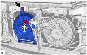

|
Bolt |

|
Connector |
Disconnect the connector.
Remove the bolt.
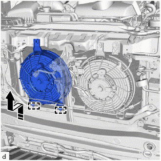
|
|
Remove in this Direction |
Detach the guide and remove the No. 2 blower assembly with shroud as shown in the illustration.
for Single Fan:
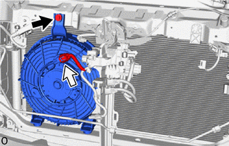
|
|
Bolt |
|
|
Connector |
Disconnect the connector.
Remove the bolt.
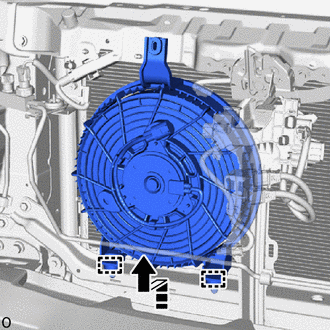
|
|
Remove in this Direction |
Detach the guide and remove the No. 2 blower assembly with shroud as shown in the illustration.
88590D
12.REMOVE NO. 1 BLOWER ASSEMBLY WITH SHROUD
except Wagon:
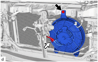
|
|
Bolt |
|
|
Connector |
Disconnect the connector.
Remove the bolt.
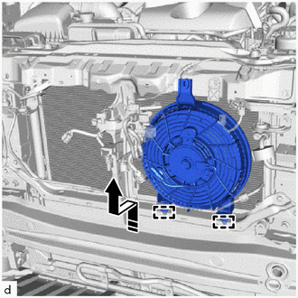
|
|
Remove in this Direction |
Detach the guide and remove the No. 1 blower assembly with shroud as shown in the illustration.
for Wagon:
|
|
Bolt |
|
|
Connector |
Disconnect the connector.
Remove the bolt.
|
|
Remove in this Direction |
Detach the guide and remove the No. 1 blower assembly with shroud as shown in the illustration.