SEAT OCCUPANT DETECTION SENSOR(for Manual Captain Seat) INSTALLATION
CAUTION / NOTICE / HINT
- CAUTION:
- ·
Wear protective gloves. Sharp areas on the parts may injure your hands.
·There is risk of injury.
- HINT:
- ·
Use the same procedure for RHD and LHD vehicles.
·The procedures listed below are for LHD vehicles.
·Use the same procedure for the RH and LH sides.
·The procedure listed below is for the LH side.
·The procedure listed below is a representative example.
·Use the same procedure for first row and second row, unless otherwise specified.
PROCEDURE

 79136C
1.INSTALL NO. 1 SEAT CUSHION PAD LH (OCCUPANT DETECTION SENSOR)
- HINT:
-
When installing a No. 1 seat cushion cover sub-assembly LH, refer to Precaution in order to prevent wrinkles from forming.
-
Click hereVehicle Interior>SEAT>FRONT SEAT ASSEMBLY (for Separate Seat Type)>PRECAUTION
| *a | Hog Ring Pliers |
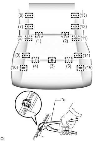
Using hog ring pliers, install the No. 1 seat cushion pad LH (occupant detection sensor) to the No. 1 seat cushion cover sub-assembly LH with 15 new hog rings in the order shown in the illustration.
- NOTICE:
- ·
Be careful not to damage the No. 1 seat cushion cover sub-assembly LH.
·Be sure to securely install the hog rings as shown in the illustration while preventing wrinkles from forming on the No. 1 seat cushion cover sub-assembly LH.
| *a | Hog Ring Pliers |
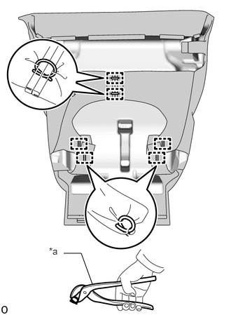
Using hog ring pliers, install 6 new hog rings.
- NOTICE:
-
Be careful not to damage the No. 1 seat cushion cover sub-assembly LH.
2.INSTALL SEPARATE TYPE REAR SEAT CUSHION COVER WITH PAD
Set the separate type rear seat cushion cover with pad on the No. 1 seat cushion frame sub-assembly LH.
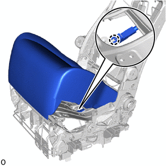
Attach the claw and install the connector of the occupant detection sensor.
Connect the connector of the occupant detection sensor.
Attach the hook and clip.
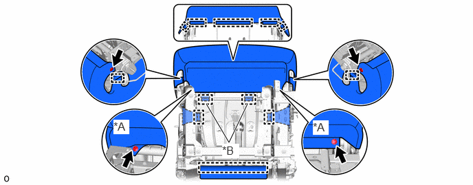
| *A | for First Row | *B | for Second Row |
for First Row:
Install the 4 clips.
for Second Row:
Install the 2 clips.
79959K
3.INSTALL NO. 2 SEAT NO. 2 LEG COVER LH (for Second Row)
79077G
4.INSTALL NO. 2 SEAT INNER LEG COVER SUB-ASSEMBLY RH (for Second Row, w/o Power Supply Unit)
79077G
5.INSTALL NO. 2 SEAT OUTER LEG COVER SUB-ASSEMBLY LH (for Second Row)
79959J
6.INSTALL NO. 2 SEAT NO. 1 LEG COVER LH (for Second Row)
79959F
7.INSTALL NO. 1 SEAT LEG COVER LH (for First Row)
79076M
8.INSTALL NO. 1 SEAT INNER LEG COVER SUB-ASSEMBLY RH (for First Row)
79076N
9.INSTALL NO. 1 SEAT OUTER LEG COVER SUB-ASSEMBLY LH (for First Row)
10.INSTALL SEPARATE TYPE REAR SEATBACK COVER WITH PAD
73390
11.INSTALL REAR SEAT 3 POINT TYPE BELT ASSEMBLY LH (ANCHOR)
73375
12.INSTALL REAR SEAT SHOULDER BELT COVER LH
72890C
13.INSTALL LH SEAT NO. 1 SEAT ARMREST ASSEMBLY LH
72880C
14.INSTALL LH SEAT NO. 1 SEAT ARMREST ASSEMBLY RH
- HINT:
-
Use the same procedure described for the LH side.
72848D
15.INSTALL NO. 1 SEAT NO. 1 ARMREST CAP LH
71826A
16.INSTALL NO. 1 SEAT INNER CUSHION MOULDING RH
78060C
17.INSTALL NO. 1 SEAT SIDE TABLE ASSEMBLY (for First Row, RH Side)
71849K
18.INSTALL SEAT SIDE TABLE ADJUSTER COVER CAP (for First Row, RH Side)
71834J
19.INSTALL NO. 1 SEAT OUTER NO. 1 RECLINING COVER LH
71324Q
20.INSTALL NO. 1 SEAT CUSHION LH (for First Row)
72526J
21.INSTALL NO. 1 SEAT RECLINING ADJUSTER RELEASE HANDLE LH
72216B
22.INSTALL NO. 1 SEAT TRACK HANDLE CONTROL LEVER LH
71849L
23.INSTALL NO. 1 SEAT ADJUSTER COVER CAP LH
24.INSTALL REAR SEAT ASSEMBLY LH
25.CONNECT CABLE TO NEGATIVE BATTERY TERMINAL (for First Row)
for 7GR-FKS:
for 1GD-FTV:
26. INITIALIZATION AFTER RECONNECTING BATTERY TERMINAL (for First Row)
Click hereGeneral>SETUP>WHEN DISCONNECTING OR RECONNECTING BATTERY TERMINAL>WORK PROCEDURE
- HINT:
-
When disconnecting and reconnecting the battery, there is an automatic learning function that completes learning when the respective system is used.
-
Click hereGeneral>SETUP>WHEN DISCONNECTING OR RECONNECTING BATTERY TERMINAL>AUTOMATIC LEARNING CHART
27. PERFORM DIAGNOSTIC SYSTEM CHECK (for First Row)
28.CHECK SRS WARNING LIGHT (for First Row)
29.INSPECT SEAT BELT WARNING SYSTEM