1GD-FTV ENGINE CONTROL MANIFOLD ABSOLUTE PRESSURE SENSOR INSTALLATION
PROCEDURE

 89421C
1.INSTALL DIESEL TURBO PRESSURE SENSOR
for Air Cooled Type Intercooler:
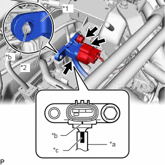
| *1 | Diesel Turbo Pressure Sensor |
| *2 | No. 3 Water By-pass Pipe Sub-assembly |
| *a | Vacuum Hose |
| *b | Protrusion |
| *c | Paint Mark |
Connect the vacuum hose to the diesel turbo pressure sensor.
- NOTICE:
-
Connect the vacuum hose so that the paint mark on the vacuum hose is aligned with the protrusions of the diesel turbo pressure sensor as shown in the illustration.
Install the diesel turbo pressure sensor with the bolt.
- Torque:
- 10 N*m (102 kgf*cm, 7 ft.*lbf)
- NOTICE:
-
Make sure the protrusion of the No. 3 water by-pass pipe sub-assembly is inserted into the hole of the diesel turbo pressure sensor.
Connect the diesel turbo pressure sensor connector.
for Water Cooled Type Intercooler:
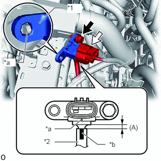
| *1 | Diesel Turbo Pressure Sensor |
| *2 | Vacuum Hose |
| *a | Protrusion |
| *b | Paint Mark |
Connect the vacuum hose to the diesel turbo pressure sensor.
- (A):
0 to 4 mm (0 to 0.157 in.)
- NOTICE:
-
Connect the vacuum hose so that the paint mark on the vacuum hose is aligned with the protrusions of the diesel turbo pressure sensor as shown in the illustration.
Install the diesel turbo pressure sensor with the bolt.
- Torque:
- 10 N*m (102 kgf*cm, 7 ft.*lbf)
- NOTICE:
-
Make sure the protrusion of the No. 3 water by-pass pipe sub-assembly is inserted into the hole of the diesel turbo pressure sensor.
Connect the diesel turbo pressure sensor connector.
12601B
2.INSTALL NO. 1 ENGINE COVER SUB-ASSEMBLY