1GD-FTV ENGINE CONTROL DIESEL THROTTLE BODY INSTALLATION
PROCEDURE

 26100G
1.INSTALL DIESEL THROTTLE BODY ASSEMBLY
for Air Cooled Type Intercooler:
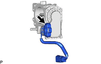
Connect the connector to install the emission control valve wire to the diesel throttle body assembly.
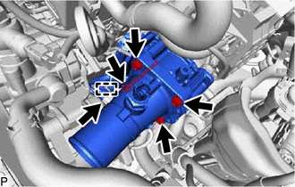
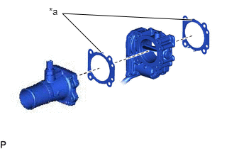
Install new 2 gaskets and the diesel throttle body assembly and intake air connector with the 4 bolts.
- Torque:
- 10 N*m (102 kgf*cm, 7 ft.*lbf)
- NOTICE:
-
 1.479,0.76 0.917,0.198 0.917,0.198 2.823,0.292 true 0.719,0.083 1.031,0.24 0.313,0.156 10 false *a
*a Claw
-
The claws of the 2 gaskets must face the diesel throttle body assembly side shown in the illustration.
Connect the connector and clamp.
for Cold Area Specification Vehicles:
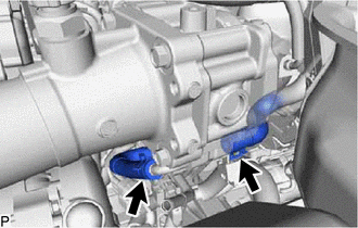
Connect the No. 11 water by-pass hose and No. 14 water by-pass hose to the diesel throttle body assembly, and slide the 2 clips to secure the hose.
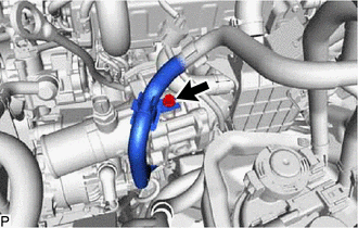
Connect the fuel hose bracket with the bolt to the diesel throttle body assembly.
- Torque:
- 8.0 N*m (82 kgf*cm, 71 in.*lbf)
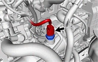
Connect the intake air temperature sensor connector.
for Water Cooled Type Intercooler:
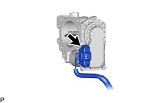
Connect the emission control valve wire connector to the diesel throttle body assembly.
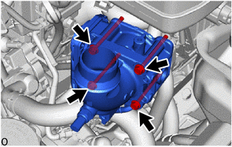
Install 2 new gaskets and the diesel throttle body assembly and intake air connector with the 4 bolts.
- Torque:
- 10 N*m (102 kgf*cm, 7 ft.*lbf)
- NOTICE:
-
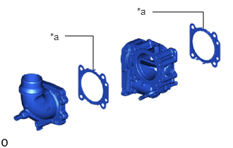 2.25,0.177 3,0.177 3,0.177 3,0.427 true 1.375,1.031 1.375,0.531 1.375,0.531 0.958,0.531 true 2.021,0.083 2.333,0.281 0.313,0.198 10 false *a 0.74,0.458 1.052,0.656 0.313,0.198 10 false *a
*a Claw
-
The claws of the 2 gaskets must face the diesel throttle body assembly side shown in the illustration.
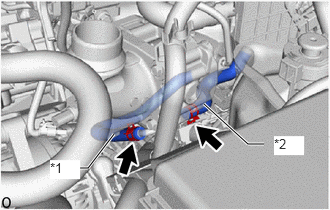
| *1 | No. 11 Water by-pass Hose |
| *2 | No. 14 Water by-pass Hose |
Connect the No. 11 water by-pass hose and No. 14 water by-pass hose to the diesel throttle body assembly, and slide the 2 clips to secure the hose.
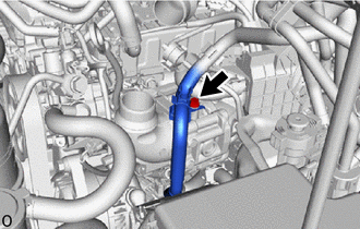
Connect the fuel hose bracket with the bolt to the diesel throttle body assembly.
- Torque:
- 8.0 N*m (82 kgf*cm, 71 in.*lbf)
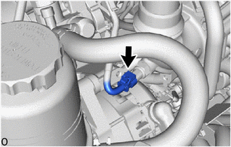
Connect the connector to the intake air temperature sensor.
17030
2.INSTALL AIR HOSE ASSEMBLY (for Water Cooled Type Intercooler)
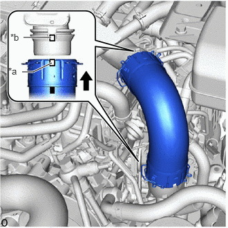
| *a | Protrusion |
| *b | Cutout of the Intercooler |
Connect the air hose assembly to the intake air connector and intercooler assembly and lock the 2 retainers.
- NOTICE:
- ·
Securely insert the retainer so that the 4 locks are engaged. Then, pull and check that the locks are engaged and that the hose cannot be pulled out.
·Align the protrusion with the cutout ofthe intercooler.
- HINT:
-
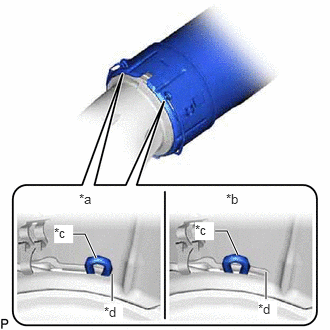 1.167,3.135 1.167,2.854 true 0.76,2.438 0.885,2.438 0.885,2.438 1,2.688 true 2.24,2.406 2.365,2.406 2.365,2.406 2.479,2.656 true 2.771,3.115 2.771,2.833 true 0.823,1.99 1.135,2.146 0.313,0.156 10 false *a 2.354,1.99 2.667,2.146 0.313,0.156 10 false *b 0.563,2.344 0.76,2.531 0.198,0.188 10 true *c 1.083,3.167 1.281,3.354 0.198,0.188 10 true *d 2.031,2.313 2.229,2.5 0.198,0.188 10 true *c 2.688,3.135 2.885,3.323 0.198,0.188 10 true *d
*a Correct *b Incorrect *c Retainer *d Stopper
-
Make sure that the retainer end contacts the stopper as shown in the illustration.
17303T
3.INSTALL AIR PIPE SUB-ASSEMBLY (for Air Cooled Type Intercooler)
25761B
4.INSTALL NO. 1 VACUUM TRANSMITTING HOSE (for Air Cooled Type Intercooler)
51405A
5.INSTALL NO. 1 ENGINE UNDER COVER SUB-ASSEMBLY
52618
6.INSTALL LOWER FRONT BUMPER ABSORBER
51406A
7.INSTALL NO. 2 ENGINE UNDER COVER SUB-ASSEMBLY (w/ No. 2 Engine Under Cover Sub-assembly)
12601B
8.INSTALL NO. 1 ENGINE COVER SUB-ASSEMBLY
for Air Cooled Type Intercooler:
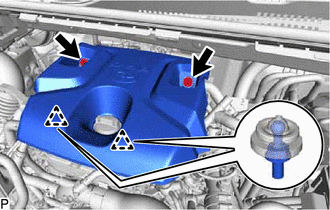
Attach the 2 clips and install the No. 1 engine cover sub-assembly to the No. 2 water by-pass pipe.
Install the No. 1 engine cover sub-assembly to the No. 1 engine cover bracket and No. 2 engine cover bracket with the 2 nuts.
- Torque:
- 21 N*m (214 kgf*cm, 15 ft.*lbf)
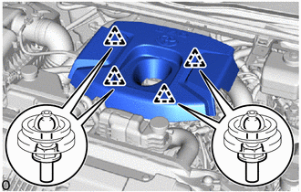
for Water Cooled Type Intercooler:
Attach the 4 clips and No. 1 engine cover sub-assembly.
9.PERFORM INITIALIZATION
w/ Urea SCR System:
Click hereEngine / Hybrid System>1GD-FTV (ENGINE CONTROL)>ECD SYSTEM (w/ Urea SCR System)>INITIALIZATION
w/ EGR Cooler:
Click hereEngine / Hybrid System>1GD-FTV (ENGINE CONTROL)>ECD SYSTEM (w/ EGR Cooler)>INITIALIZATION
w/o EGR Cooler:
Click hereEngine / Hybrid System>1GD-FTV (ENGINE CONTROL)>ECD SYSTEM (w/o EGR Cooler)>INITIALIZATION
for Water Cooled Type Intercooler: