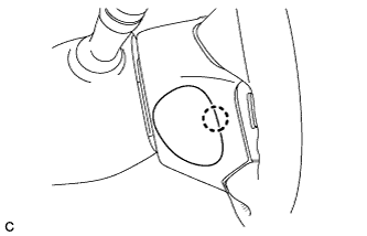
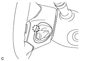
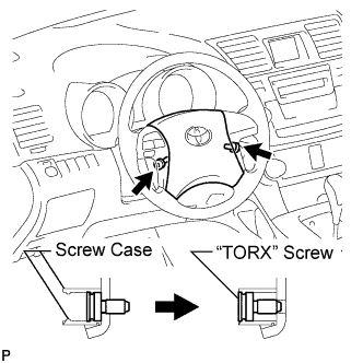
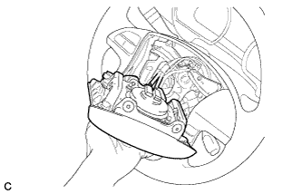
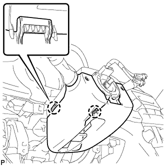
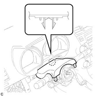
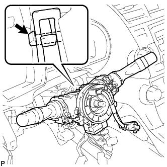
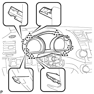
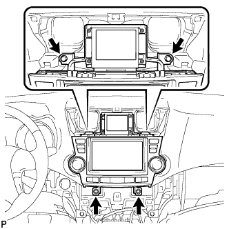
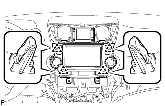
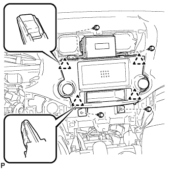
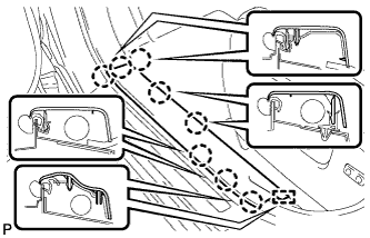
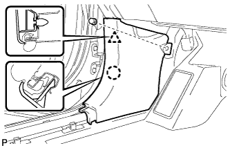
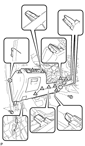
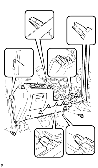
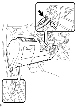
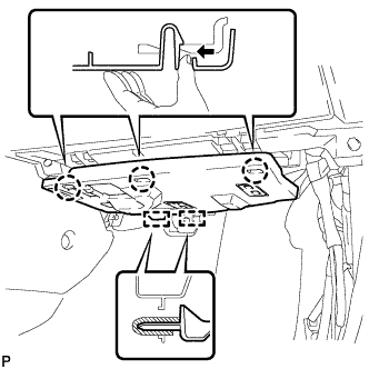
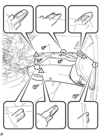
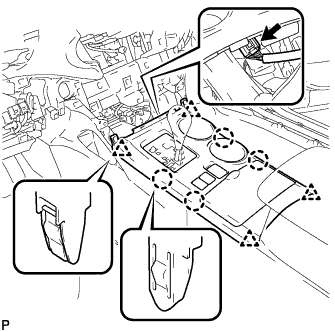
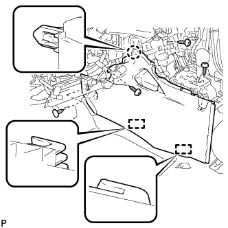
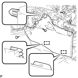
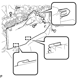
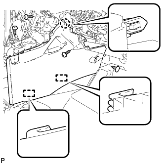
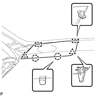
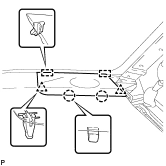
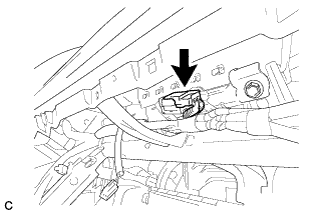
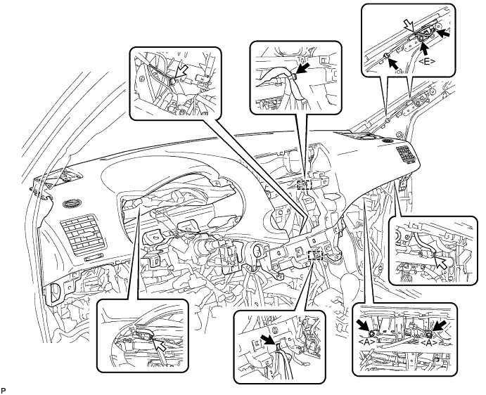
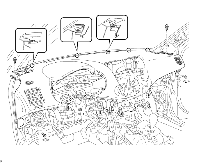
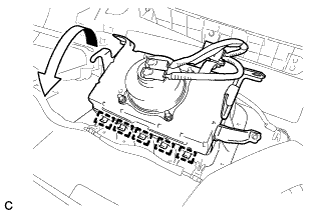
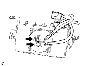
Disengage the 4 claws and 4 clips, and remove the instrument cluster finish panel assembly.
11.
REMOVE COMBINATION METER ASSEMBLY
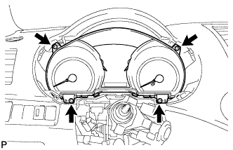
Remove the 4 screws <F>.
Disconnect the connector and remove the combination meter assembly.
12.
REMOVE CENTER INSTRUMENT PANEL REGISTER ASSEMBLY
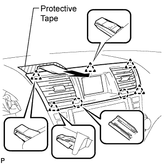
Apply protective tape to the areas shown in the illustration.
Using a moulding remover, disengage the 2 claws and 5 clips, and then remove the center instrument panel register assembly as shown in the illustration.
13.
REMOVE CENTER INSTRUMENT CLUSTER FINISH PANEL ASSEMBLY (w/o Smart Entry and Start System)
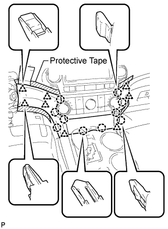
Apply protective tape to the areas shown in the illustration.
Using a moulding remover, disengage the 10 claws and 8 clips starting from the upper part of the center instrument cluster finish panel assembly.
NOTICE:
Do not pull on the small storage compartment lid. Doing so may cause damage.
Disconnect each connector and remove the center instrument cluster finish panel assembly.
14.
REMOVE CENTER INSTRUMENT CLUSTER FINISH PANEL ASSEMBLY (w/ Smart Entry and Start System)
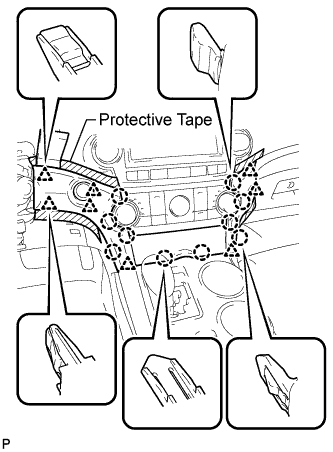
Apply protective tape to the areas shown in the illustration.
Using a moulding remover, disengage the 10 claws and 8 clips starting from the upper part of the center instrument cluster finish panel assembly.
NOTICE:
Do not pull on the small storage compartment lid. Doing so may cause damage.
Disconnect each connector and remove the center instrument cluster finish panel assembly.
15.
REMOVE HEATER CONTROL AND ACCESSORY ASSEMBLY (for Manual Air Conditioning System)
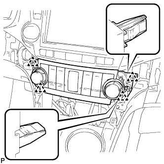
Disengage the 4 clips and remove the heater control and accessory assembly.
Disconnect the connector.
16.
REMOVE AIR CONDITIONING CONTROL ASSEMBLY (for Automatic Air Conditioning System)
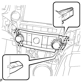
Disengage the 4 clips and remove the air conditioning control assembly.
Disconnect the connector.
17.
REMOVE RADIO RECEIVER ASSEMBLY WITH BRACKET (w/o Navigation System)
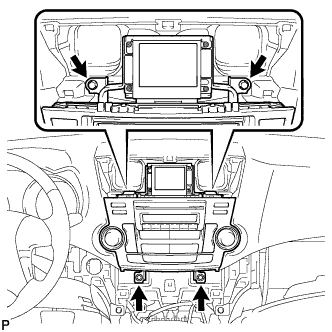
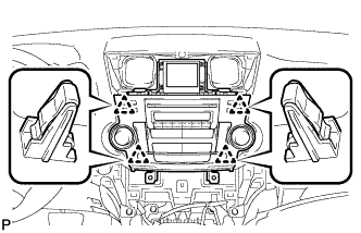
Remove the 4 bolts.
Pull the radio receiver assembly with bracket toward the rear of the vehicle and disengage the 4 clips.
Disconnect each connector and remove the radio receiver assembly with bracket.
18.
REMOVE NAVIGATION RECEIVER ASSEMBLY WITH BRACKET (w/ Navigation System)
Remove the 4 bolts.
Pull the navigation receiver assembly with bracket toward the rear of the vehicle and disengage the 4 clips.
Disconnect each connector and remove the navigation receiver assembly with bracket.
19.
REMOVE INTEGRATION CONTROL AND PANEL ASSEMBLY WITH BRACKET (w/o Radio Receiver)
Remove the 4 bolts <D>.
Disengage the 4 clips.
Disconnect each connector and remove the integration control and panel assembly with bracket.
20.
REMOVE FRONT DOOR SCUFF PLATE LH
Disengage the 8 claws and guide, and remove the front door scuff plate LH.
21.
REMOVE COWL SIDE TRIM SUB-ASSEMBLY LH
Remove the clip.
Disengage the clip and claw, and remove the cowl side trim sub-assembly LH.
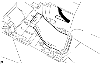
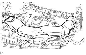
Remove the No. 2 console box duct as shown in the illustration.
30.
REMOVE LOWER REAR CONSOLE BOX
Remove the lower rear console box.
31.
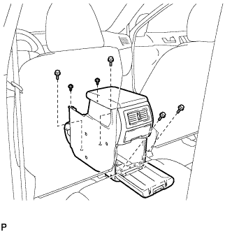
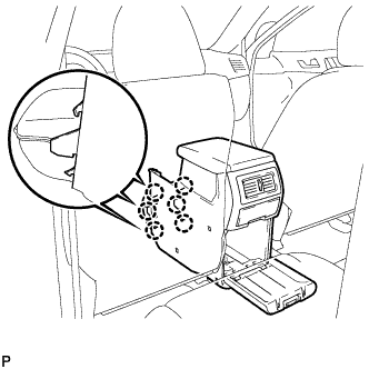
REMOVE CONSOLE BOX ASSEMBLY (w/o Rear Air Conditioning System)
Remove the 4 bolts and 2 screws.
Disengage the 6 claws and remove the console box assembly.
32.
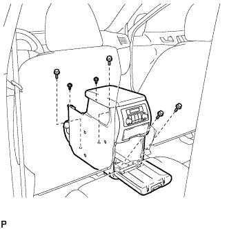
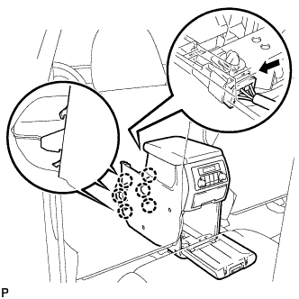
REMOVE CONSOLE BOX ASSEMBLY (w/ Rear Air Conditioning System)
Remove the 4 bolts and 2 screws.
Disconnect the connector.
Disengage the 6 claws, and remove the console box assembly.
33.
REMOVE FRONT NO. 1 CONSOLE BOX INSERT (for LHD)
Using a clip remover, remove the 2 clips.
Remove the 3 screws <F>.
Disengage the claw and 2 guides, and then remove the front No. 1 console box insert.
34.
REMOVE FRONT NO. 1 CONSOLE BOX INSERT (for RHD)
Using a clip remover, remove the clip.
Remove the 3 screws <F>.
Disengage the claw and 2 guides, and then remove the front No. 1 console box insert.
35.
REMOVE FRONT NO. 2 CONSOLE BOX INSERT (for LHD)
Using a clip remover, remove the clip.
Remove the 3 screws <F>.
Disengage the claw and 2 guides, and then remove the front No. 2 console box insert.
36.
REMOVE FRONT NO. 2 CONSOLE BOX INSERT (for RHD)
Using a clip remover, remove the clip.
Remove the 3 screws <F>.
Disengage the claw and 2 guides, and then remove the front No. 2 console box insert.
37.
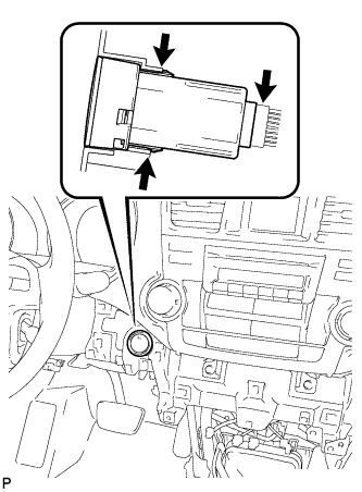
REMOVE ENGINE SWITCH (w/ Smart Entry and Start System)
Disconnect the switch connector.
Disengage the 2 claws and remove the switch.
38.
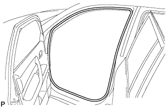
DISCONNECT FRONT DOOR OPENING TRIM WEATHERSTRIP LH
Remove the front door opening trim weatherstrip LH.
39.
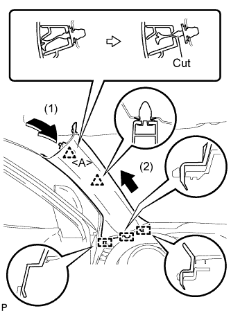
REMOVE FRONT PILLAR GARNISH LH
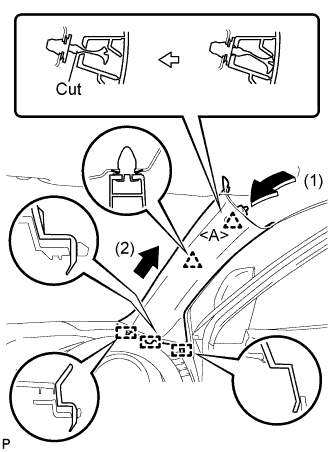
Pull the upper part of the garnish toward the inside of the cabin and disengage the 2 clips.
Cut off the clip <A>.
Disengage the 3 guides and remove the front pillar garnish LH.
Remove the clip <A>.
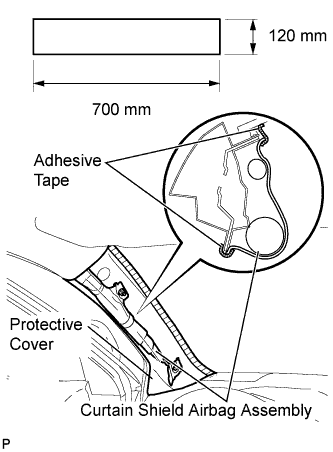
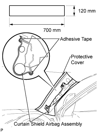
Protect the curtain shield airbag assembly.
Cover the airbag with a 700 mm (27.56 in.) x 120 mm (4.72 in.) cloth or piece of nylon and fix the ends of the cover with tape, as shown in the illustration.
NOTICE:
Cover the curtain shield airbag with a protective cover as soon as the front pillar garnish is removed.
40.
DISCONNECT FRONT DOOR OPENING TRIM WEATHERSTRIP RH
HINT:
Use the same procedure for the RH side and the LH side (Click here).
41.
REMOVE FRONT PILLAR GARNISH RH
Pull the upper part of the garnish toward the inside of the cabin and disengage the 2 clips.
Cut off the clip <A>.
Disengage the 3 guides and remove the front pillar garnish RH.
Remove the clip <A>.
Protect the curtain shield airbag assembly.
Cover the airbag with a 700 mm (27.56 in.) x 120 mm (4.72 in.) cloth or piece of nylon and fix the ends of the cover with tape, as shown in the illustration.
NOTICE:
Cover the curtain shield airbag with a protective cover as soon as the front pillar garnish is removed.