Home › STEERING › STEERING COLUMN › STEERING LOCK SYSTEMUnlock Position Sensor Signal Circuit
Circuit diagnosis · Vehicles built Aug 2008 – Jun 2010
Versions by build date: May 2007 – Jul 2008 Aug 2008 – Jun 2010 from Jul 2010
DESCRIPTION
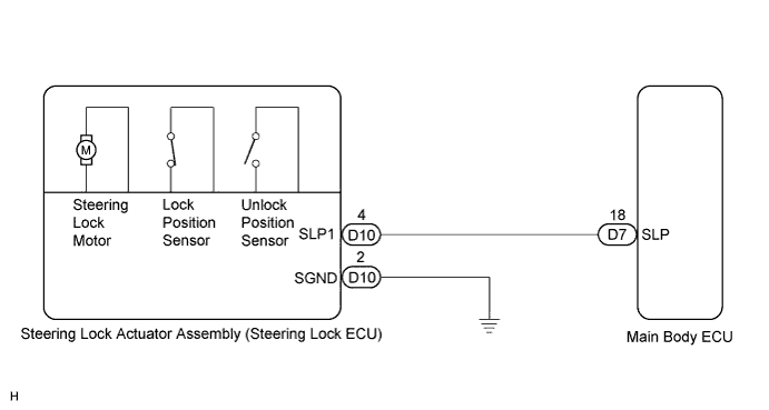
The unlock position sensor is one of the components of the steering lock actuator assembly. The sensor switch contact closes when the steering lock is released. The steering lock release signal is then sent to the main body ECU. Receiving the signal, the ECU permits engine start. (This prevents the engine from being started with the steering locked.) WIRING DIAGRAM
INSPECTION PROCEDURE
1. INSPECT STEERING LOCK ACTUATOR ASSEMBLY (STEERING LOCK ECU)
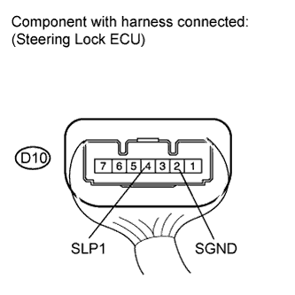
Measure the voltage according to the value(s) in the table below.
Standard voltage:
Tester Connection
Switch Condition
Specified Condition
D10-4 (SLP1) - D10-2 (SGND)
Engine switch off
Engine switch on (ACC or IG)
Below 1 V
NG
OK
2. CHECK HARNESS AND CONNECTOR (STEERING LOCK ACTUATOR ASSEMBLY - MAIN BODY ECU)
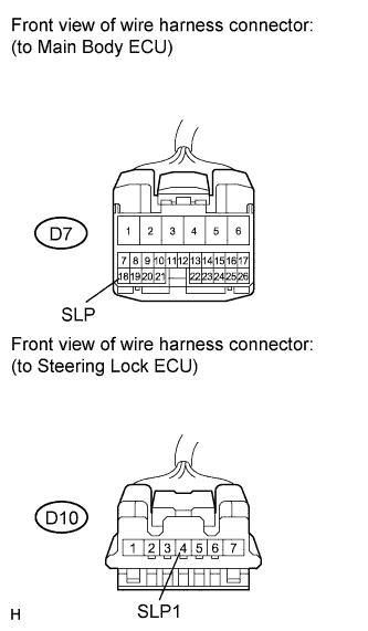
Disconnect the D10 connector from the steering lock actuator assembly. Disconnect the D7 connector from the main body ECU.
Measure the resistance according to the value(s) in the table below.
Standard resistance:
Tester Connection
Switch Condition
Specified Condition
D10-4 (SLP1) - D7-18 (SLP)
Always
Below 1 Ω
D10-4 (SLP1) - Body ground
Always
10 kΩ or higher
NG
REPAIR OR REPLACE HARNESS OR CONNECTOR
OK
PROCEED TO NEXT CIRCUIT INSPECTION SHOWN IN PROBLEM SYMPTOMS TABLE (Click here )