REMOVAL
Removal / installation · Vehicles built Aug 2008 – Jun 2010
Versions by build date: May 2007 – Jul 2008 Aug 2008 – Jun 2010 from Jul 2010
- HINT:
- Use the same procedures for the RH side and LH side.
- The procedures listed below are for the LH side.
| 1.
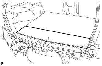
REMOVE DECK BOARD ASSEMBLY
|
 |
- Remove the deck board assembly.
| 2.
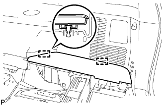
REMOVE NO. 3 DECK BOARD SUB-ASSEMBLY (w/ Tonneau Cover)
|
|
- Disengage the 2 guides and remove the No. 3 deck board sub-assembly.
| 3.
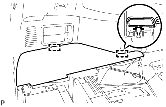
REMOVE NO. 2 DECK BOARD SUB-ASSEMBLY (w/ Tonneau Cover)
|
|
- Disengage the 2 guides and remove the No. 2 deck board sub-assembly.
| 4.
REMOVE TONNEAU COVER ASSEMBLY (w/ Tonneau Cover)
|
|
Remove the tonneau cover assembly.
| 5.
REMOVE REAR MAT
|
|
- Remove the rear mat.
| 6.
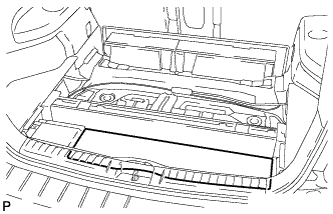
REMOVE DECK TRIM SERVICE HOLE COVER |
|
| 7.
REMOVE LOWER SPARE WHEEL CARRIER HINGE COVER |
|
| 9.
REMOVE SPARE WHEEL CARRIER LOCK COVER |
|
| 11.
SEPARATE REAR STABILIZER LINK ASSEMBLY LH |
|
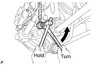
- Remove the nut and separate the rear stabilizer link assembly LH from the rear stabilizer bar.
- HINT:
- If the ball joint turns together with the nut, use a hexagon wrench (5 mm) to hold the stud bolt.
| 12.
SEPARATE REAR STABILIZER LINK ASSEMBLY RH |
|
- HINT:
- Perform the same procedure as the LH side.
| 13.
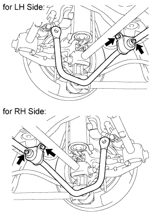
REMOVE REAR STABILIZER BAR
|
|
- Remove the 4 bolts and rear stabilizer bar.
| 14.
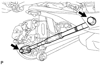
REMOVE REAR NO. 2 SUSPENSION ARM ASSEMBLY |
|
Remove the bolt and the nut, and separate the rear No. 2 suspension arm assembly from the rear axle carrier sub-assembly.
- NOTICE:
- Since a stopper nut is used, loosen the bolt.
Remove the bolt and the rear No. 2 suspension arm assembly.
| 15.
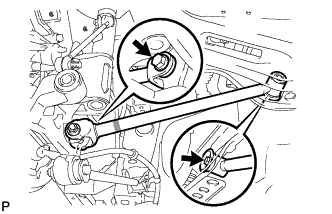
REMOVE REAR NO. 1 SUSPENSION ARM ASSEMBLY |
|
Remove the bolt and the nut, and separate the rear No. 1 suspension arm assembly from the rear axle carrier sub-assembly.
- NOTICE:
- Since a stopper nut is used, loosen the bolt.
Remove the bolt and the rear No. 1 suspension arm assembly.