INSTALLATION
Removal / installation · Vehicles built Aug 2008 – Jun 2010
Versions by build date: May 2007 – Jul 2008 Aug 2008 – Jun 2010 from Jul 2010
| 1.
TEMPORARILY INSTALL REAR STABILIZER BAR |
 |
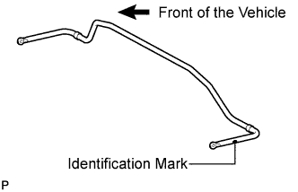
- Temporarily install the rear stabilizer bar with the identification mark positioned on the left side of the vehicle.
| 2.
TEMPORARILY INSTALL REAR STABILIZER BAR BRACKET LH (for Front Side) |
|
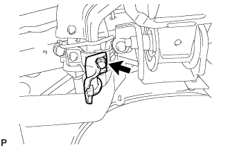
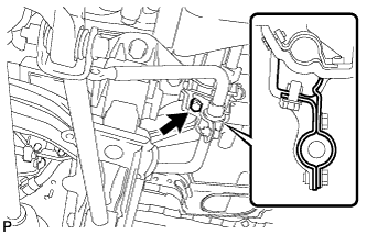
- Temporarily install the rear stabilizer bar bracket LH (front side) with the bolt.
- HINT:
- Loosely tighten the bolt so that the bracket can be moved by hand.
| 3.
TEMPORARILY INSTALL REAR STABILIZER BAR BRACKET RH (for Front Side) |
|
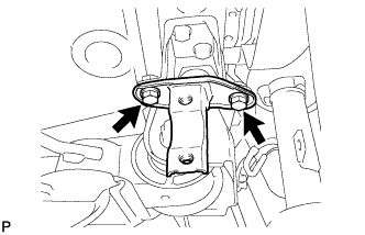
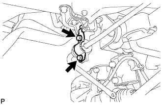
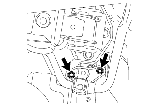
- Temporarily install the rear stabilizer bar bracket RH (front side) with the 2 bolts.
- HINT:
- Loosely tighten the bolts so that the bracket can be moved by hand.
| 4.
INSTALL REAR STABILIZER BUSHING (for LH Side) |
|
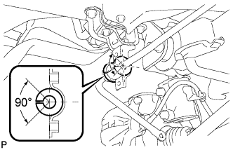
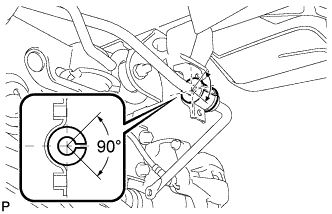
- Install the rear stabilizer bushing (LH side) to the rear stabilizer bar.
- NOTICE:
- Make sure that the cutout of the rear stabilizer bushing is positioned within the range shown in the illustration.
| 5.
INSTALL REAR STABILIZER BUSHING (for RH Side) |
|
- Install the rear stabilizer bushing (RH side) to the rear stabilizer bar.
- NOTICE:
- Make sure that the cutout of the rear stabilizer bushing is positioned within the range shown in the illustration.
| 6.
INSTALL REAR STABILIZER BAR BRACKET LH (for Rear Side) |
|
- Install the rear stabilizer bar bracket LH (rear side) with the 2 bolts.
-
Torque:
- 19 N*m{
194 kgf*cm
, 14 ft.*lbf
}
| 7.
INSTALL REAR STABILIZER BAR BRACKET RH (for Rear Side) |
|
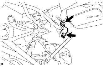
- Install the rear stabilizer bar bracket RH (rear side) with the 2 bolts.
-
Torque:
- 19 N*m{
194 kgf*cm
, 14 ft.*lbf
}
| 8.
FULLY TIGHTEN REAR STABILIZER BAR BRACKET LH (for Front Side) |
|
- Fully tighten the bolt.
-
Torque:
- 54 N*m{
550 kgf*cm
, 40 ft.*lbf
}
| 9.
FULLY TIGHTEN REAR STABILIZER BAR BRACKET RH (for Front Side) |
|
- Fully tighten the 2 bolts.
-
Torque:
- 19 N*m{
194 kgf*cm
, 14 ft.*lbf
}
| 10.
INSTALL REAR STABILIZER LINK ASSEMBLY LH |
|
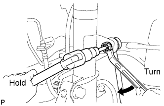
- Install the rear stabilizer link assembly LH to the rear shock absorber with coil spring LH with the nut.
-
Torque:
- 39 N*m{
400 kgf*cm
, 29 ft.*lbf
}
- HINT:
- If the ball joint turns together with the nut, use a hexagon wrench (5 mm) to hold the stud bolt.
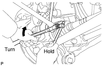
- Install the rear stabilizer link assembly LH to the rear stabilizer bar with the nut.
-
Torque:
- 39 N*m{
400 kgf*cm
, 29 ft.*lbf
}
- HINT:
- If the ball joint turns together with the nut, use a hexagon wrench (5 mm) to hold the stud bolt.
| 11.
INSTALL REAR STABILIZER LINK ASSEMBLY RH |
|
- HINT:
- Perform the same procedure as the LH side.
| 12.
INSTALL TAIL EXHAUST PIPE ASSEMBLY
|
|
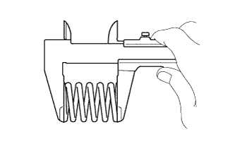
- Using vernier calipers, measure the free length of the compression spring.
Minimum
|
40.5 mm (1.59 in.)
|
- HINT:
- If the length is less than the minimum, replace the compression spring.
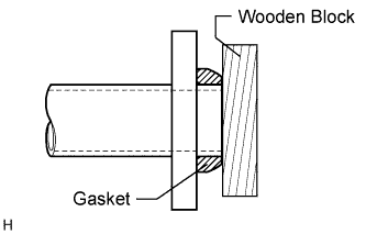
- Using a plastic-faced hammer and wooden block, tap in a new gasket until its surface is flush with the center exhaust pipe assembly.
- NOTICE:
- Tap in the gasket in the correct direction.
- Do not reuse the removed gasket.
- Do not push in the gasket while installing the tail exhaust pipe assembly.
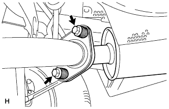
Connect the exhaust pipe support, and install the tail exhaust pipe assembly.
- Install the 2 compression springs and 2 bolts.
-
Torque:
- 48 N*m{
489 kgf*cm
, 35 ft.*lbf
}
| 13.
INSPECT FOR EXHAUST GAS LEAK
|
|
If exhaust gas is leaking, repair the leak. Replace damaged or worn parts as necessary.
| 14.
INSTALL REAR WHEELS |
|
-
Torque:
- 103 N*m{
1050 kgf*cm
, 76 ft.*lbf
}
| 15.
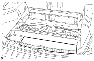
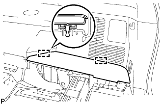
INSTALL SPARE WHEEL CARRIER LOCK COVER |
|
| 17.
INSTALL LOWER SPARE WHEEL CARRIER HINGE COVER |
|
| 18.
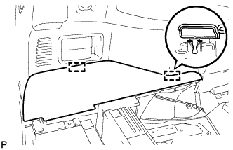
INSTALL DECK TRIM SERVICE HOLE COVER |
|
| 19.
INSTALL REAR MAT
|
|
- Install the rear mat.
| 20.
INSTALL TONNEAU COVER ASSEMBLY (w/ Tonneau Cover)
|
|
Install the tonneau cover assembly.
| 21.
INSTALL NO. 2 DECK BOARD SUB-ASSEMBLY (w/ Tonneau Cover)
|
|
- Engage the 2 guides and install the No. 2 deck board sub-assembly.
| 22.
INSTALL NO. 3 DECK BOARD SUB-ASSEMBLY (w/ Tonneau Cover)
|
|
- Engage the 2 guides and install the No. 3 deck board sub-assembly.
| 23.
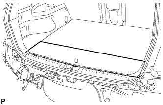
INSTALL DECK BOARD ASSEMBLY
|
|
- Install the deck board sub-assembly.