Diagnosis Circuit
Circuit diagnosis · Vehicles built from May 2007
DESCRIPTION
This circuit is used to read the DTCs that are output from the transponder key ECU assembly with the intelligent tester.WIRING DIAGRAM
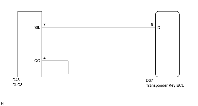

INSPECTION PROCEDURE
- NOTICE:
- If the transponder key ECU is replaced, register the key and ECU communication ID.
| 1. CHECK HARNESS AND CONNECTOR (TRANSPONDER KEY ECU - DLC3) |

Disconnect the transponder key ECU connector.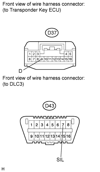
Measure the resistance according to the value(s) in the table below.
- Standard resistance:
Tester Connection
Condition
Specified Condition
D37-9 (D) - D43-7 (SIL)
Always
Below 1 Ω
D37-9 (D) - Body ground
Always
10 kΩ or higher
|
|
||||

| OK | |
 |
| 2. CHECK HARNESS AND CONNECTOR (DLC3 - BODY GROUND) |
Measure the resistance according to the value(s) in the table below.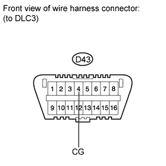
- Standard resistance:
Tester Connection
Condition
Specified Condition
D43-4 (CG) - Body ground
Always
Below 1 Ω
|
|
||||
| OK | ||
 |
||
| ||