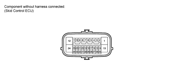
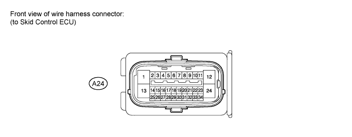
Standard:
Terminal No. (Symbols)
|
Wiring Color
|
Terminal Description
|
Condition
|
Specified Condition
|
A24-1 (GND1) - Body ground
|
W-B - Body ground
|
Skid control ECU ground
|
Always
|
Below 1 Ω
|
A24-2 (STP) - Body ground
|
L - Body ground
|
Stop light switch input
|
Stop light switch ON → OFF
(Brake pedal depressed → released)
|
8 to 14 V
→ Below 1.5 V
|
A24-12 (+BS) - Body ground
|
R - Body ground
|
Solenoid relay power supply
|
Always
|
11 to 14 V
|
A24-13 (GND2) - Body ground
|
W-B - Body ground
|
Pump motor ground
|
Always
|
Below 1 Ω
|
A24-21 (BZ) - Body ground
|
Y - Body ground
|
Skid control buzzer output
|
Ignition switch on (IG), buzzer not sounding
|
6 to 10 V
|
A24-22 (STP2) - Body ground
|
L - Body ground
|
Stop light control relay input
|
Stop light switch ON → OFF
(Brake pedal depressed → released)
|
8 to 14 V
→ Below 1.5 V
|
A24-24 (+BM) - Body ground
|
B - Body ground
|
Motor relay power supply
|
Always
|
11 to 14 V
|
A24-26 (HDCS) (*1) - Body ground
|
W - Body ground
|
Downhill assist control switch input
|
Downhill assist control switch is pushed in → released
|
Below 1 Ω → 10 kΩ or higher
|
A24-27 (FSW+) - Body ground
|
GR - Body ground
|
Brake pedal load sensing switch input
|
Brake pedal load sensing switch OFF → ON
(Brake pedal depressed → released)
|
950 to 1050 Ω → 203 to 223 Ω
|
A24-29 (PKB) - Body ground
|
BR - Body ground
|
Parking brake switch input
|
Ignition switch on (IG), parking brake switch OFF → ON
|
Below 1 Ω → 10 kΩ or higher
|
A24-30 (CSW) - Body ground
|
G - Body ground
|
VSC OFF switch input
|
VSC OFF switch held ON → OFF (Released)
|
Below 25 Ω → 10 kΩ or higher
|
A24-31 (STPO) - Body ground
|
P - Body ground
|
Stop light control relay output
|
Ignition switch on (IG)
|
11 to 14 V
|
A24-34 (IG1) - Body ground
|
O - Body ground
|
ECU power supply
|
Ignition switch on (IG)
|
11 to 14 V
|