Home › SECURITIES › THEFT DETERRENT › THEFT DETERRENT SYSTEM (w/o Smart Entry and Start System)Horn Circuit
Circuit diagnosis · Vehicles built from Jul 2010
Versions by build date: May 2007 – Jul 2008 Aug 2008 – Jun 2010 from Jul 2010
DESCRIPTION
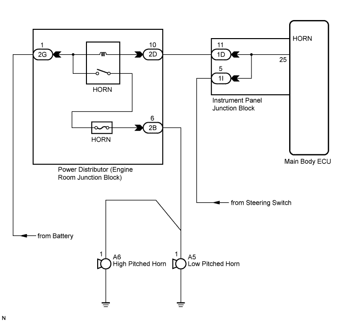
When the theft deterrent system is switched from the armed state to the alarm sounding state, the main body ECU transmits a signal to cause the horn to sound at 0.4 second intervals. WIRING DIAGRAM
INSPECTION PROCEDURE
1. INSPECT HORNS
Press the horn switch and check if the horns sound.
Result:
Result
Proceed to
Horns sound
A
Horns do not sound
B
B
A
2. PERFORM ACTIVE TEST USING INTELLIGENT TESTER
Connect the intelligent tester to the DLC3.
Turn the ignition switch to the ON position.
Turn the intelligent tester main switch on.
Select the item below in the Active Test and then check that the horns operate.
Main Body:
Tester Display
Test Part
Control Range
Diagnostic Note
Vehicle Horn
Vehicle horns
ON / OFF
-
OK:
The vehicle horns sound and stop correctly when operating them through the intelligent tester.
NG
OK
PROCEED TO NEXT CIRCUIT INSPECTION SHOWN IN PROBLEM SYMPTOMS TABLE (Click here )
3. CHECK HARNESS AND CONNECTOR (INSTRUMENT PANEL JUNCTION BLOCK - ENGINE ROOM JUNCTION BLOCK)
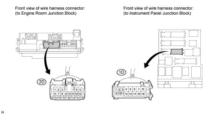
Disconnect the ID instrument panel junction block connector and 2D engine room junction block connector.
Measure the resistance according to the value(s) in the table below.
Standard resistance:
Tester Connection
Condition
Specified Condition
1D-11 - 2D-10
Always
Below 1 Ω
1D-11 - Body ground
Always
10 kΩ or higher
NG
REPAIR OR REPLACE HARNESS OR CONNECTOR
OK
REPLACE MAIN BODY ECU (INSTRUMENT PANEL JUNCTION BLOCK)