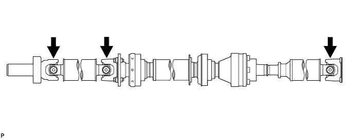
REASSEMBLY
Removal / installation · Vehicles built from May 2007
| 1. INSTALL SLIDING SHAFT DUST COVER, |

Using SST and a press, install a new sliding shaft dust cover.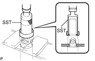

- SST
- 09316-60011
- NOTICE:
- Be careful not to damage the sliding shaft dust cover.
| 2. INSTALL NO. 1 CENTER SUPPORT BEARING ASSEMBLY |
Set the No. 1 center support bearing assembly on the intermediate shaft as shown in the illustration.
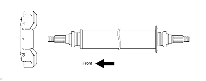
Install a new washer to the intermediate shaft.
Align the matchmarks on the front flange and shaft, and place the front flange on the shaft.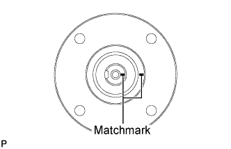
Using SST to hold the front flange, press the No. 1 center support bearing assembly into position by tightening down a new nut and plate washer.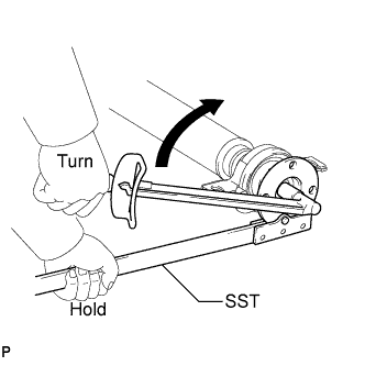
- SST
- 09330-00021
- Torque:
- 182 N*m{ 1850 kgf*cm , 134 ft.*lbf }
Loosen the nut.
Tighten the nut again.
- Torque:
- 69 N*m{ 700 kgf*cm , 51 ft.*lbf }
Using a chisel and a hammer, stake the nut.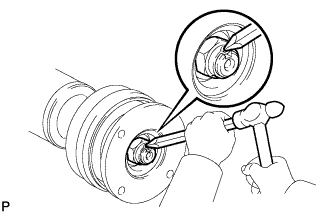
| 3. INSTALL NO. 2 CENTER SUPPORT BEARING ASSEMBLY |
Set the No. 2 center support bearing assembly on the shaft as shown in the illustration.
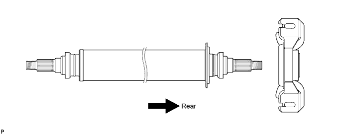
Install a new washer to the intermediate shaft.
Align the matchmarks on the rear flange and intermediate shaft, and place the flange on the shaft.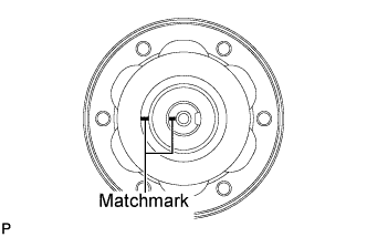
Using SST to hold the front flange, press the No. 2 center support bearing assembly into position by tightening down a new nut and plate washer.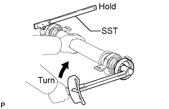
- SST
- 09330-00021
- Torque:
- 182 N*m{ 1850 kgf*cm , 134 ft.*lbf }
Loosen the nut.
Tighten the nut again.
- Torque:
- 69 N*m{ 700 kgf*cm , 51 ft.*lbf }
Using a chisel and a hammer, stake the nut.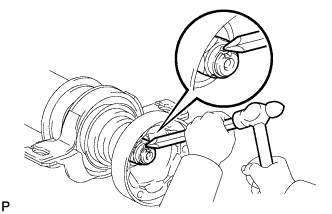
| 4. INSTALL REAR PROPELLER SHAFT |
Align the matchmarks on the intermediate shaft and rear propeller shaft, and then install the 2 washers and 6 bolts.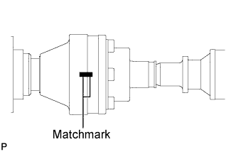
Using a hexagon wrench (6 mm), temporarily tighten the 6 bolts.
| 5. INSTALL PROPELLER SHAFT ASSEMBLY |
Align the matchmarks on the propeller shaft assembly and front flange.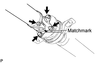
Install the propeller shaft assembly to the front flange with the 4 bolts, 4 washers and 4 nuts.
- Torque:
- 74 N*m{ 750 kgf*cm , 54 ft.*lbf }
Check that each joint of the propeller with center bearing shaft assembly is facing the direction shown in the illustration.