INSPECTION
Inspection · Vehicles built from May 2007
| INSPECT TURN SIGNAL FLASHER ASSEMBLY |

Disconnect the D11 turn signal flasher assembly connector.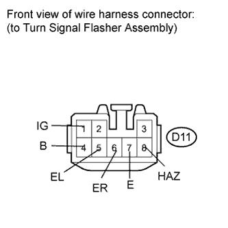

Measure the voltage according to the value(s) in the table below.
- Standard voltage:
Tester Connection
Condition
Specified Condition
D11-1 (IG) - Body ground
Ignition switch off
Below 1 V
Ignition switch on (IG)
11 to 14 V
D11-4 (B) - Body ground
Always
11 to 14 V
Measure the resistance according to the value(s) in the table below.
- Standard resistance:
Tester Connection
Condition
Specified Condition
D11-5 (EL) - Body ground
Turn signal switch OFF
11 kΩ or higher
Turn signal switch in LH position
Below 1 Ω
D11-6 (ER) - Body ground
Turn signal switch OFF
11 kΩ or higher
Turn signal switch in RH position
Below 1 Ω
D11-7 (E) - Body ground
Always
Below 1 Ω
D11-8 (HAZ) - Body ground
Hazard warning switch OFF
11 kΩ or higher
Hazard warning switch ON
Below 1 Ω
Reconnect the D11 turn signal flasher assembly connector.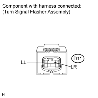
Measure the voltage according to the value(s) in the table below.
- Standard voltage:
Tester Connection
Condition
Specified Condition
D11-2 (LR) - Body ground
Hazard warning switch OFF
Below 1 V
Hazard warning switch ON
11 to 14 V (60 to 120 times per minute)
Turn signal switch OFF
Below 1 V
Ignition switch on (IG) and turn signal switch in RH position
11 to 14 V (60 to 120 times per minute)
D11-3 (LL) - Body ground
Hazard warning switch OFF
Below 1 V
Hazard warning switch ON
11 to 14 V (60 to 120 times per minute)
Turn signal switch OFF
Below 1 V
Ignition switch on (IG) and turn signal switch in LH position
11 to 14 V (60 to 120 times per minute)