2007-2013 Highlander Kluger · Service Manual BODY ELECTRICAL

Power Source Circuit

Circuit diagnosis · Vehicles built May 2007 – Jul 2008

Versions by build date: May 2007 – Jul 2008 Aug 2008 – Jun 2010 from Jul 2010

DESCRIPTION

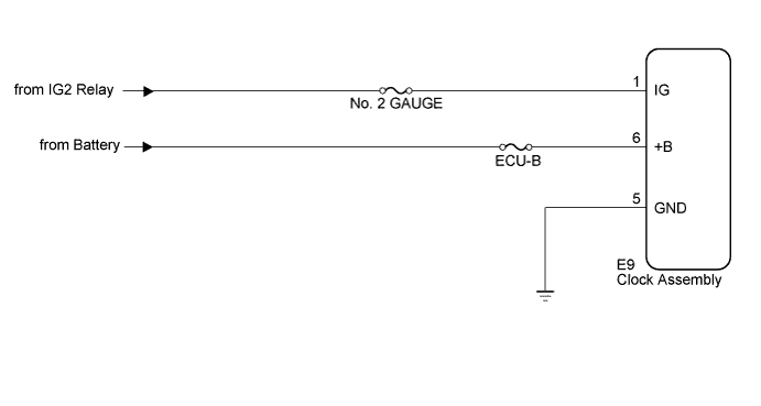
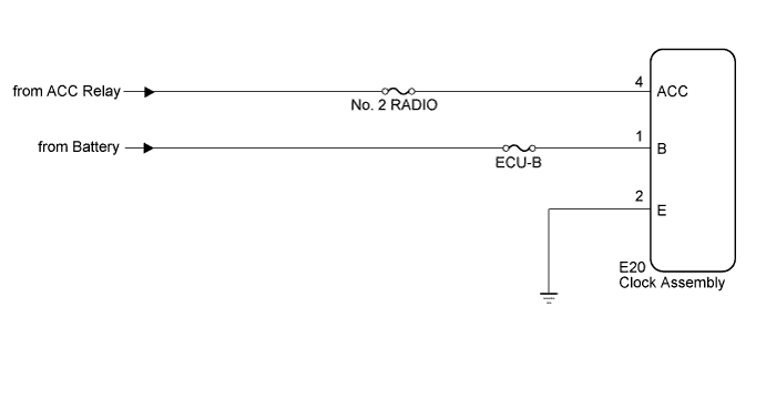
This circuit is the power source for the clock assembly. This circuit provides two types of power sources; one is a constant power source mainly used as a backup power source, and the other is a power source mainly used for signal transmission.

HINT:
If the clock assembly displays "1:00" when the ignition switch off, then on (IG) again, the B (*1) or +B (*2) terminal has a malfunction.
The maximum clock assembly margin of error is -4 to 4 seconds per day when the temperature is between -20°C (-4°F) and 60°C (140°F).
  1. *1: w/o Multi-information Display
  2. *2: w/ Multi-information Display


WIRING DIAGRAM


w/o Multi-information Display
E152379E10

w/ Multi-information Display
E152379E11

INSPECTION PROCEDURE


1. CHECK HARNESS AND CONNECTOR

  1. E152380E03
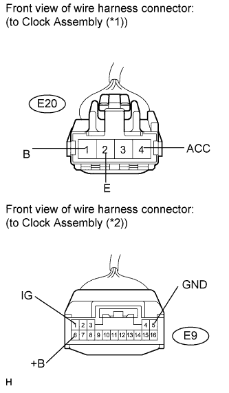
    Disconnect the E20 (*1) or E9 (*2) connector.

  1. Measure the voltage according to the value(s) in the table below.
    Standard voltage:
    Tester Connection
    Condition
    Specified Condition
    E20-1 (B) (*1) - Body ground
    Always
    11 to 14 V
    E9-6 (+B) (*2) - Body ground
    Always
    11 to 14 V
    E20-4 (ACC) (*1) - Body ground
    Ignition switch on (ACC)
    11 to 14 V
    E9-1 (IG) (*2) - Body ground
    Ignition switch on (IG)
    11 to 14 V

    *1: w/o Multi-information Display*2: w/ Multi-information Display

  1. Measure the resistance according to the value(s) in the table below.

    Standard resistance:
    Tester Connection
    Condition
    Specified Condition
    E20-2 (E) (*1) - Body ground
    Always
    Below 1 Ω
    E9-5 (GND) (*2) - Body ground
    Always
    Below 1 Ω

    *1: w/o Multi-information Display*2: w/ Multi-information Display

    Result:
    Result
    Proceed to
    OK (w/o Multi-information Display)
    A
    OK (w/ Multi-information Display)
    B
    NG
    C


B
REPLACE CLOCK ASSEMBLY (w/ Multi-information Display) (Click here)

C
REPAIR OR REPLACE HARNESS OR CONNECTOR
A

REPLACE CLOCK ASSEMBLY (w/o Multi-information Display) (Click here)


← Illumination Circuit (from Jul 2012)Power Source Circuit (Aug 2008 – Jun 2010) →