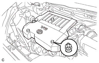
Hold the front of the V-bank cover sub-assembly and raise it to disengage the 2 clips on the front of the V-bank cover sub-assembly. Continue rising the V-bank cover sub-assembly to disengage the clip on the rear of the V-bank cover sub-assembly and remove the V-bank cover sub-assembly.
NOTICE:
Attempting to disengage both front and rear clips at the same time may cause the V-bank cover sub-assembly to break.
2.
REMOVE ENGINE UNDER COVER ASSEMBLY
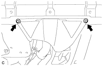
Remove the 2 bolts and engine under cover assembly RR.
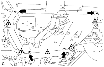
Remove the 2 bolts, 2 screws, 5 clips and engine under cover assembly.
3.
REMOVE NO. 1 ENGINE UNDER COVER
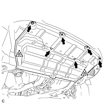
Remove the 6 bolts, 2 clips and No. 1 engine under cover.
4.
DRAIN ENGINE COOLANT
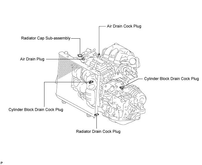
Loosen the radiator drain cock plug.
HINT:
Collect the coolant in a container and dispose of it according to the regulations in your area.
Remove the radiator cap sub-assembly from the radiator assembly.
NOTICE:
Do not remove the radiator cap sub-assembly while the engine and radiator are still hot. Pressurized, hot engine coolant and steam may be released and cause serious burns.
Loosen the 2 cylinder block drain cock plugs.
5.
REMOVE COOL AIR INTAKE DUCT SEAL
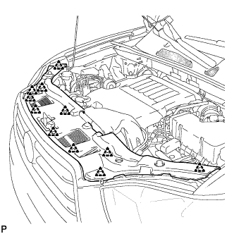
Remove the 11 clips and cool air intake duct seal.
6.
REMOVE BATTERY
CAUTION:
Wait at least 90 seconds after disconnecting the cable from the negative (-) battery terminal to prevent airbag and seat belt pretensioner activation.
NOTICE:
When disconnecting the cable, some systems need to be initialized after the cable is reconnected (Click here).
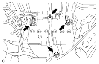
Loosen the nut, and disconnect the negative battery terminal.
Loosen the nut, and disconnect the positive battery terminal.
Loosen the nut, and remove the bolt and battery clamp.
Remove the battery and battery tray.
7.
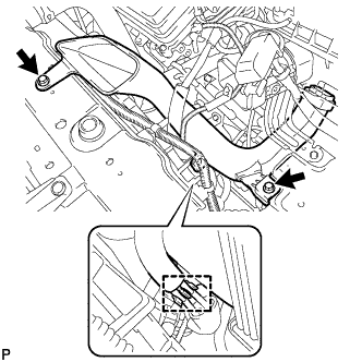
REMOVE NO. 2 AIR CLEANER INLET
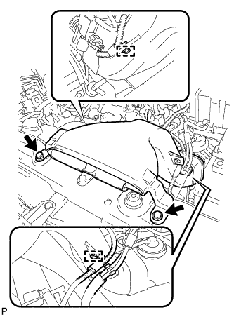
Disconnect the 2 vacuum switching valve clamps.
Disconnect the 2 vacuum hoses.
Remove the 2 bolts and No. 2 air cleaner inlet.
8.
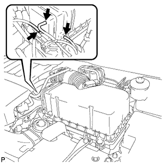
REMOVE NO. 1 AIR CLEANER INLET
Disconnect the 2 vacuum hoses, and remove the 2 bolts and No. 1 air cleaner inlet.
9.
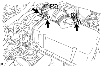
REMOVE AIR CLEANER CAP SUB-ASSEMBLY
Disconnect the 3 vacuum hoses.
Loosen the No. 1 air cleaner hose clamp.
Disconnect the hose clamps and No. 2 ventilation hose.
Disconnect the mass air flow meter connector.
Release the 2 clips, and remove the 2 bolts.
Remove the air cleaner cap sub-assembly and air cleaner filter element.
10.
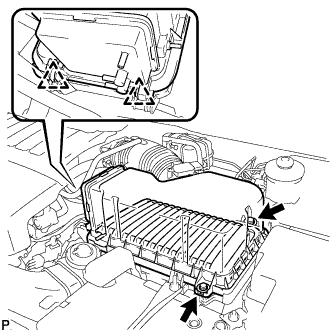
REMOVE AIR CLEANER CASE SUB-ASSEMBLY
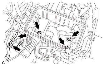
Remove the 3 bolts, disconnect the hose and the connector, and remove the air cleaner case sub-assembly.
11.
REMOVE ENGINE COOLANT TEMPERATURE SENSOR
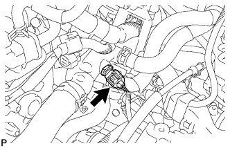
Disconnect the engine coolant temperature sensor connector.
Remove the engine coolant temperature sensor and gasket.