INSTALLATION
Removal / installation · Vehicles built from Jul 2010
Versions by build date: May 2007 – Jul 2008 Aug 2008 – Jun 2010 from Jul 2010
| 1. INSTALL WIRELESS DOOR LOCK BUZZER |

Connect the connector.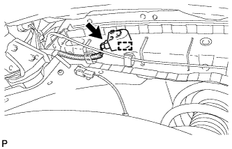

Install the wireless door lock buzzer with the clamp.
| 2. INSTALL FRONT FENDER LINER LH |
Install the front fender liner LH with the 5 clips and 8 screws.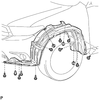
Install the bolt.
Install 3 new grommets.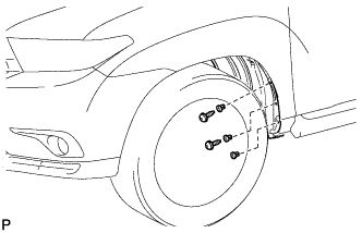
Using a 4 mm hexagon wrench, install the 2 screws.
Install the screw and 2 pin hold clips.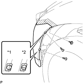
Text in Illustration *1
Correct
*2
Incorrect
- NOTICE:
- Insert the pin hold clip with the slot aligned vertically. Do not rotate the clip after inserting it. After installation, confirm that the slot is aligned vertically.
| 3. INSTALL FRONT FENDER MOULDING SUB-ASSEMBLY LH |
Clean the vehicle body surface.
Using a heat light, heat the vehicle body surface.
Remove the front fender side protector from the vehicle body.
Wipe off any tape adhesive residue with cleaner.
Clean the front fender moulding sub-assembly (if reusing the front fender moulding sub-assembly).
Using a heat light, heat the front fender moulding sub-assembly.
Remove the double-sided tape from the front fender moulding sub-assembly.
Wipe off any tape adhesive residue with cleaner.
Apply new double-sided tape to the front fender moulding sub-assembly.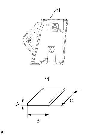
Text in Illustration *1
Double-sided Tape
Item
Dimension
A
1.2 mm (0.0472 in.)
B
3.0 mm (0.1181 in.)
C
72.0 mm (2.83 in.)
Install 2 new No. 4 clips on the front fender moulding sub-assembly.
Install a new pad on the front fender moulding sub-assembly.
Install the front fender moulding sub-assembly.
Using a heat light, heat the vehicle body and the front fender moulding sub-assembly.
Remove the release paper from the front fender moulding sub-assembly.
- HINT:
- After removing the release paper, keep the exposed adhesive free from foreign matter.
Engage the 3 clips and install the front fender moulding sub-assembly.
Using a 4 mm hexagon wrench, install the screw.
Install the clip.