Use the same procedures for the LH side and RH side.
The following procedure is for the LH side.
If the sensor rotor needs to be replaced, replace it together with the front drive outboard joint shaft assembly. (Click here) (Click here)
1.
INSTALL FRONT SPEED SENSOR
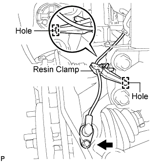
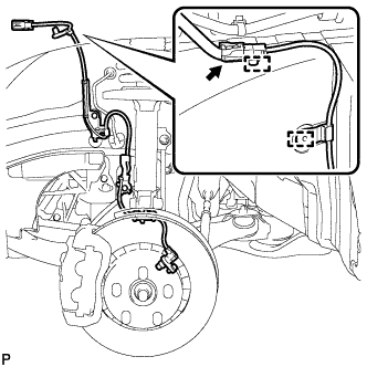
Install the resin clamp and the front speed sensor with bolt.
Torque:
8.0 N*m{
82 kgf*cm
, 71 in.*lbf
}
NOTICE:
Prevent foreign matter from attaching to the front speed sensor tip.
Firmly insert the front speed sensor body into the knuckle before tightening the bolt.
After installing the front speed sensor to the knuckle, make sure that there is no clearance between the front speed sensor stay and knuckle. Also make sure that no foreign matter is stuck between the parts.
Before installing the clamp, firmly insert the points of the clamp into the installation holes.
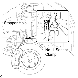
Temporarily install the No. 1 sensor clamp.
NOTICE:
Be sure to insert the No. 1 sensor clamp claw into the stopper hole while installing the No. 1 sensor clamp.
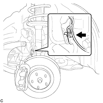
Install the front flexible hose and the No. 1 sensor clamp together to the shock absorber with the bolt.
Torque:
19 N*m{
194 kgf*cm
, 14 ft.*lbf
}
NOTICE:
Do not twist the wire harness for the front speed sensor when installing it.
A bolt tightens the brake flexible hose and front speed sensor together. Make sure that the flexible hose is positioned over the front speed sensor.
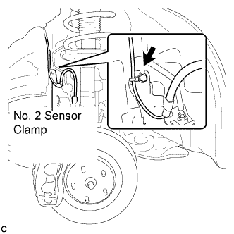
Install the No. 2 sensor clamp to the body with the bolt.
Torque:
5.0 N*m{
51 kgf*cm
, 44 in.*lbf
}
Install the 2 clamps and connect the front speed sensor connector.
2.
INSTALL FRONT FENDER LINER
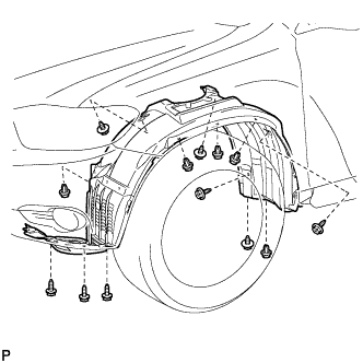
Install the front fender liner LH with the 5 clips and 8 screws.
Install 2 new grommets.
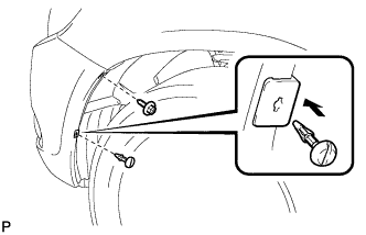
Using a 4 mm hexagon wrench, install the 2 screws.
Install the screw and pin hold clip.
Torque:
3.0 N*m{
31 kgf*cm
, 27 in.*lbf
}
3.
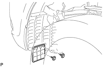
INSTALL FRONT WHEEL OPENING EXTENSION PAD
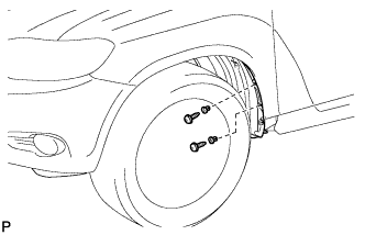
Install the front wheel opening extension pad with the 2 screws.
4.
INSTALL FRONT FENDER MOULDING SUB-ASSEMBLY LH
Clean the vehicle body surface.
Using a heat light, heat the vehicle body surface.
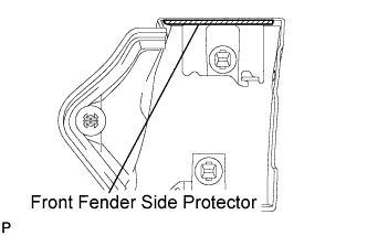
Remove the front fender side protector from the vehicle body.
Wipe off any tape adhesive residue with cleaner.
Clean the front fender moulding sub-assembly. (If reusing the front fender moulding sub-assembly)
Using a heat light, heat the front fender moulding sub-assembly.
Remove the front fender side protector from the front fender moulding sub-assembly.
Wipe off any tape adhesive residue with cleaner.
Install a new front fender side protector to the the front fender moulding sub-assembly.
Install 2 new No. 4 clips on the front fender moulding sub-assembly.
Install a new pad on the front fender moulding sub-assembly.
Install the front fender moulding sub-assembly.
Using a heat light, heat the vehicle body and the front fender moulding sub-assembly.
Remove the release paper from the front fender moulding sub-assembly.
HINT:
After removing the release paper, keep the exposed adhesive free from foreign matter.
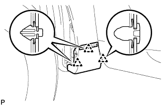
Engage the 3 clips and install the front fender moulding sub-assembly.
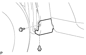
Using a 4 mm hexagon wrench, install the screw.
Install the clip.
5.
INSTALL NO. 1 ENGINE UNDER COVER
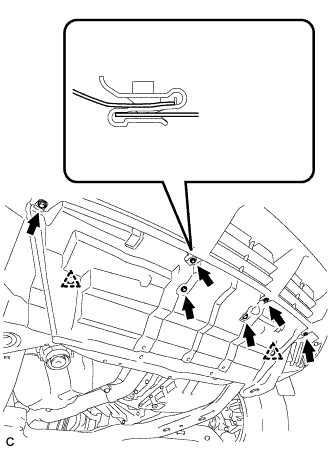
Install the No. 1 engine under cover with the 6 bolts and 2 clips.
6.
INSTALL FRONT WHEEL
Torque:
103 N*m{
1050 kgf*cm
, 76 ft.*lbf
}
7.
CONNECT CABLE TO NEGATIVE BATTERY TERMINAL
NOTICE:
When disconnecting the cable, some systems need to be initialized after the cable is reconnected. (Click here)