2007-2013 Highlander Kluger · Service Manual BODY

INSTALLATION

Removal / installation · Vehicles built from Jul 2010

Versions by build date: May 2007 – Jul 2008 Aug 2008 – Jun 2010 from Jul 2010


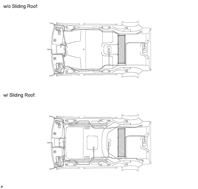
1. INSTALL REAR ROOF SIDE RAIL PAD LH (w/ Sliding Roof)

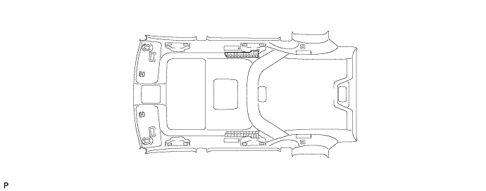
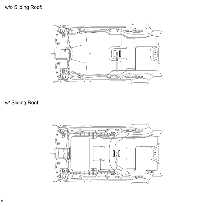
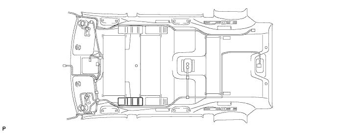
  1. Align the markings on the roof headlining assembly with the rear roof side rail pad LH and install the pad using hot melt glue to the location shown in the illustration.

    B175182


2. INSTALL REAR ROOF SIDE RAIL PAD RH (w/ Sliding Roof)

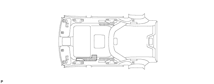
  1. Align the markings on the roof headlining assembly with the rear roof side rail pad RH and install the pad using hot melt glue to the location shown in the illustration.

    B175181


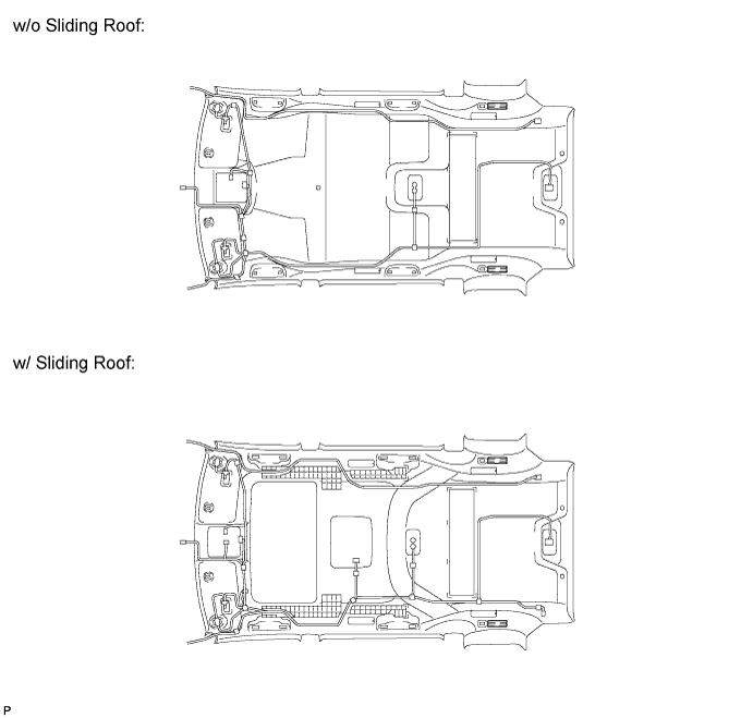
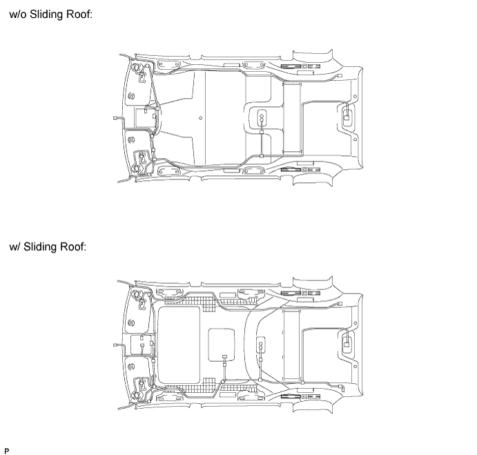
3. INSTALL ROOF SIDE RAIL GARNISH PAD LH (w/ Sliding Roof)

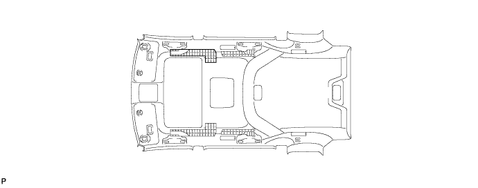
  1. Align the markings on the roof headlining assembly with the roof side rail garnish pad LH and install the pad using hot melt glue to the location shown in the illustration.

    B175180


4. INSTALL ROOF SIDE RAIL GARNISH PAD RH (w/ Sliding Roof)

  1. Align the markings on the roof headlining assembly with the roof side rail garnish pad RH and install the pad using hot melt glue to the location shown in the illustration.

    B175179


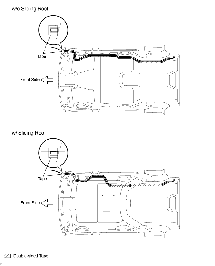
5. INSTALL NO. 2 ANTENNA CORD SUB-ASSEMBLY

HINT:
The double-sided tape and tape are not available as supply parts. If these tapes still have enough adhesion to secure the roof headlining and antenna cord, reuse the tapes. If the roof headlining has been replaced with a new one, or if the tape and/or the double-sided tape is no longer sticky, apply new tape following the procedures below.

  1. Apply new double-sided tape.

    E150570E01

    1. Remove the double-sided tape from the roof headlining assembly.

    2. Peel off the appropriate amount of new double-sided tape. Be careful not to touch the adhesive surface.

    3. Apply the double-sided tape to the roof headlining while aligning the tape with the markings on the roof headlining assembly.

    4. Peel off the backing sheet from the double-sided tape.

  1. Install the antenna cord to the roof headlining assembly from the front of the vehicle.

    E150569E01

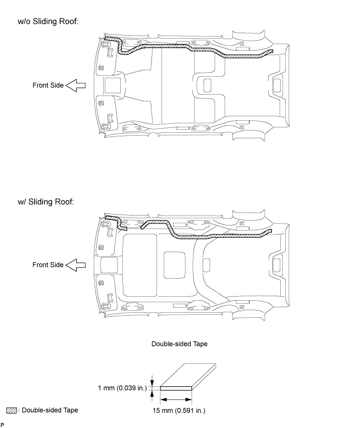
  1. Put the strips of the tape back to the positions shown in the illustration in order to secure the antenna cord to the roof headlining assembly.

    HINT:
    For the right front corner of the roof headlining assembly, align the marking tape on the antenna cord with the protrusion of the roof headlining, and wrap tape around the antenna cord and roof headlining assembly once or twice to securely hold them.


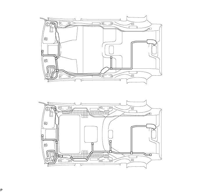
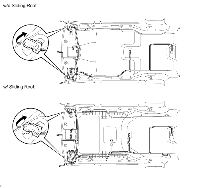
6. INSTALL NO. 1 ROOF WIRE

  1. Peel off the release paper from the double-sided tape.

    B175187

  1. w/ Vanity Light:

    1. Turn the visor connectors clockwise approximately 90° to install the connectors to the roof headlining assembly.

  1. Attach the No. 1 roof wire along the double-sided tape so that the marking surface of the wire harness faces downward.

    NOTICE:
    Securely attach the No. 1 roof wire. Failure to do so may cause abnormal noise.
    B173686E01


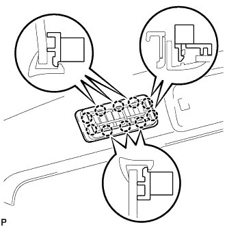
7. INSTALL NO. 1 AIR OUTLET REGISTER ASSEMBLY (w/ Rear Air Conditioning System)

  1. B175153
    Engage the 10 claws and install the No. 1 air outlet register assembly into the roof side air outlet register.


8. INSTALL NO. 2 ROOF HEADLINING SUPPORT

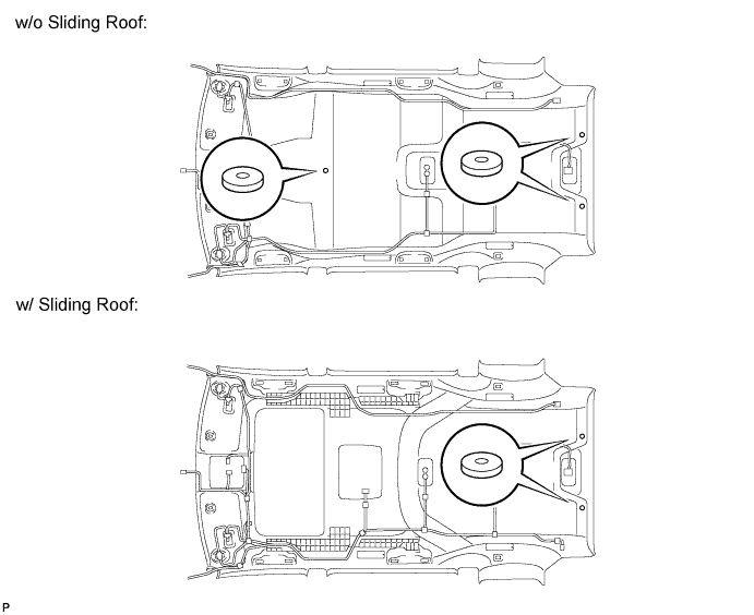
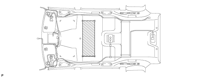
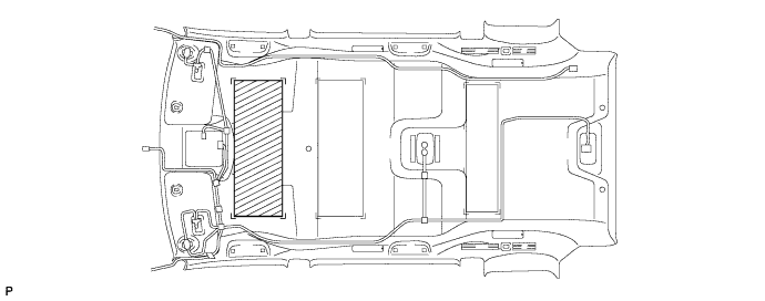
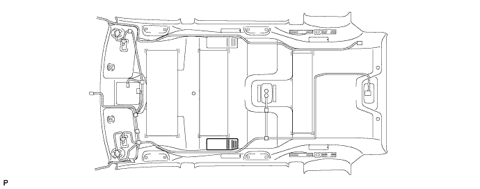
  1. Align the markings on the roof headlining assembly with the No. 2 roof headlining support(s) and install the headlining supports using hot melt glue to the location shown in the illustration.

    B173286E01


9. INSTALL NO. 4 ROOF SILENCER PAD

  1. Align the markings on the roof headlining assembly with the No. 4 roof silencer pad and install the silencer pad using hot melt glue to the location shown in the illustration.

    B263822E01


10. INSTALL NO. 2 ROOF HEADLINING PAD

  1. Align the markings on the roof headlining assembly with the 2 No. 2 roof headlining pads and install the pads using hot melt glue to the location shown in the illustration.

    B263821E01


11. INSTALL ROOF HEADLINING PAD

  1. Align the markings on the roof headlining assembly with the 2 roof headlining pads and install the pads using hot melt glue to the location shown in the illustration.

    B263820E01


12. INSTALL NO. 1 ROOF HEADLINING SUPPORT

  1. Align the markings on the roof headlining assembly with the 2 No. 1 roof headlining supports and install the headlining supports using hot melt glue to the location shown in the illustration.

    B263819E01


13. INSTALL NO. 2 ROOF SILENCER PAD (w/o Sliding Roof)

  1. Align the markings on the roof headlining assembly with the No. 2 roof silencer pad and install the silencer pad using hot melt glue to the location shown in the illustration.

    B263818


14. INSTALL NO. 1 ROOF SILENCER PAD (w/o Sliding Roof)

  1. Align the markings on the roof headlining assembly with the No. 1 roof silencer pad and install the silencer pad using hot melt glue to the location shown in the illustration.

    B263817


15. INSTALL REAR NO. 2 SIDE RAIL SPACER LH (w/o Sliding Roof)

  1. Align the markings on the roof headlining assembly with the rear No. 2 side rail spacer LH and install the spacer using hot melt glue as shown in the illustration.

    B263816


16. INSTALL REAR NO. 2 SIDE RAIL SPACER RH (w/o Sliding Roof)

HINT:
Use the same procedure for the RH side and the LH side.


17. INSTALL FRONT SIDE RAIL SPACER LH (w/o Sliding Roof)

  1. Align the markings on the roof headlining assembly with the front side rail spacer LH and install the spacer using hot melt glue as shown in the illustration.

    B263815


18. INSTALL FRONT SIDE RAIL SPACER RH (w/o Sliding Roof)

HINT:
Use the same procedure for the RH side and the LH side.


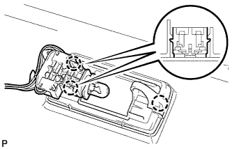
19. INSTALL VANITY LIGHT ASSEMBLY (w/ Vanity Light)

  1. B126818E05
    Engage the 3 claws and install the vanity light assembly.


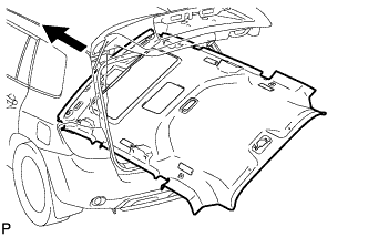
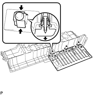
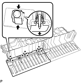
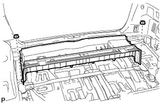
20. INSTALL ROOF HEADLINING ASSEMBLY (w/o Sliding Roof)

  1. B173271
    Pull the roof headlining assembly into the vehicle through the back door.

    NOTICE:
    Do not damage the roof headlining assembly or body interior.

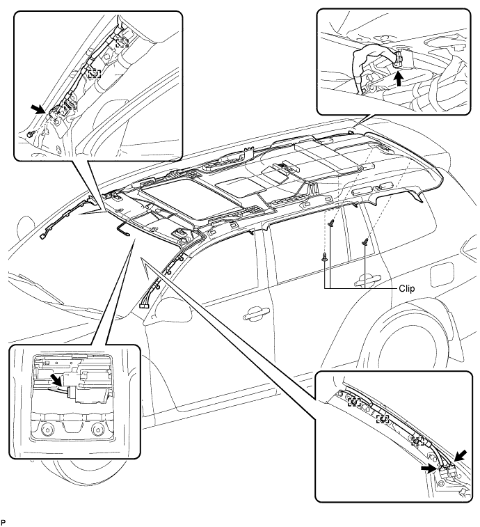
  1. Install the 4 clips.

  1. Connect the No. 2 antenna cord sub-assembly connector to the rear pillar RH.

  1. Connect the No. 2 antenna cord sub-assembly connectors and engage the 3 clamps to the front pillar RH.

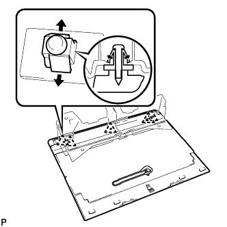
  1. Install the No. 2 antenna cord sub-assembly to the front pillar RH with the bolt.

  1. Connect the No. 1 roof wire connector and engage the 3 clamps to the front pillar LH.

    B263813E01

    NOTICE:
    After installation, make sure that the back door weatherstrip does not interfere with the roof headlining assembly.


21. INSTALL ROOF HEADLINING ASSEMBLY (w/ Sliding Roof)

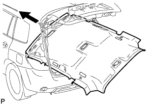
  1. B173274
    Pull the roof headlining assembly into the vehicle through the back door.

    NOTICE:
    Do not damage the roof headlining assembly or body interior.

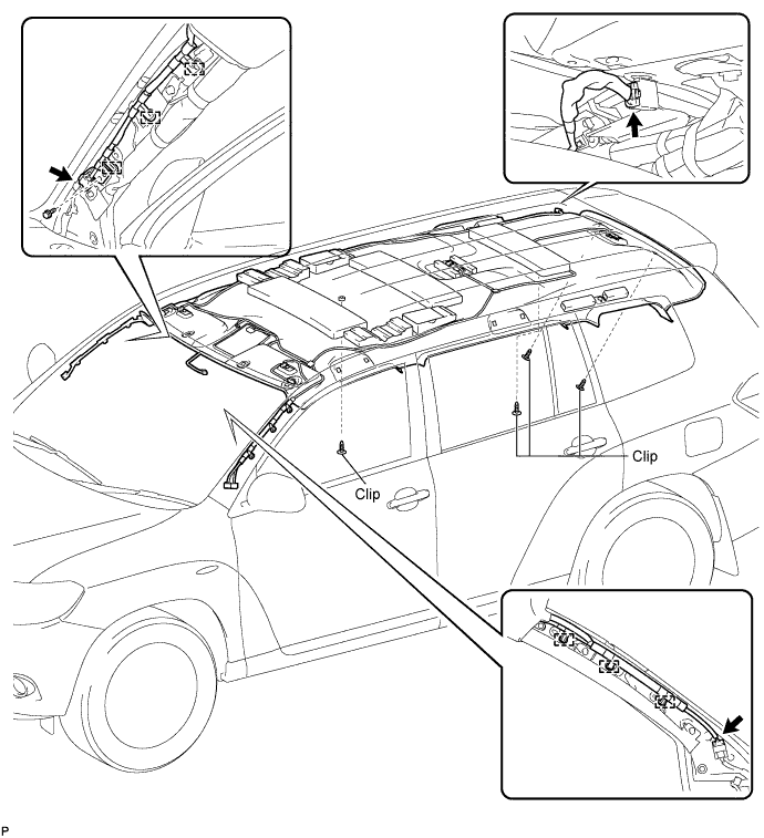
  1. Install the 3 clips.

  1. Connect the sliding roof drive gear connector.

  1. Connect the No. 2 antenna cord sub-assembly connector to the rear pillar RH.

  1. Connect the No. 2 antenna cord sub-assembly connector and engage the 3 clamps to the front pillar RH.

  1. Install the No. 2 antenna cord sub-assembly to the front pillar RH with the bolt.

  1. w/ Rear Seat Entertainment System:

    1. Connect the No. 1 roof wire connector to the rear pillar LH.

  1. Connect the No. 1 roof wire connectors and engage the 3 clamps to the front pillar LH.

    B263814E01

    NOTICE:
    After installation, make sure that the back door weatherstrip does not interfere with the roof headlining assembly.


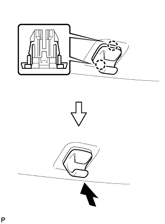
22. INSTALL VISOR HOLDER

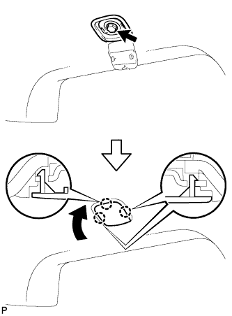
  1. B151383
    Engage the 2 claws.

  1. Push in the visor holder as shown in the illustration.

    HINT:
    Use the same procedure for the RH side and the LH side.


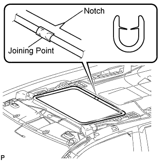
23. INSTALL SUN ROOF OPENING TRIM MOULDING (w/ Sliding Roof)

  1. B175148E01
    Align the joining point of the moulding with the notch of the roof headlining assembly, and install the sun roof opening trim moulding.

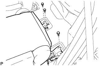
    NOTICE:
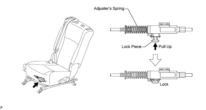
    After installation, check that the corners fit correctly.


24. INSTALL ROOF HEADLINING TRIM CLIP STOPPER

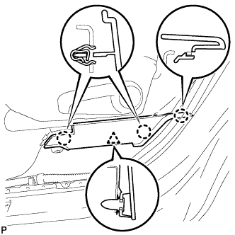
  1. B173594
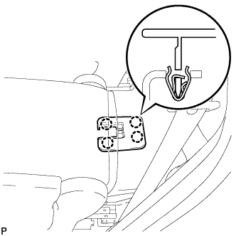
    Install the roof headlining trim clip stopper with the bolt.

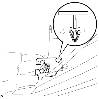
  1. Engage the 3 claws.

    HINT:
    Use the same procedure for the RH side and the LH side.


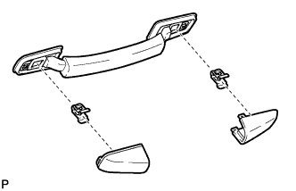
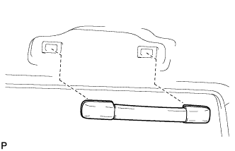
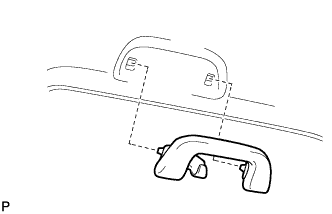
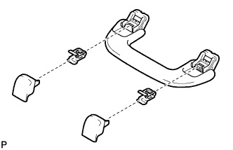
25. INSTALL ASSIST GRIP ASSEMBLY (w/ Sliding Roof)

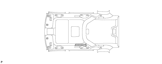
  1. B173259
    Assemble the assist grip assembly as shown in the illustration.

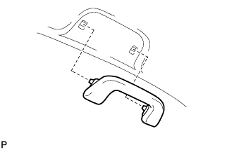
  1. B173260
    Install the assist grip assembly.

    HINT:
    Use the same procedure for the other 4 assist grips.


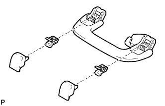
26. INSTALL REAR ASSIST GRIP SUB-ASSEMBLY (w/o Sliding Roof)

  1. B131970
    Assemble the rear assist grip sub-assembly as shown in the illustration.

  1. B167237
    Install the rear assist grip sub-assembly.

    HINT:
    Use the same procedure for the other 4 assist grips.


27. INSTALL FRONT ASSIST GRIP SUB-ASSEMBLY (w/o Sliding Roof)

  1. B125984
    Assemble the front assist grip sub-assembly as shown in the illustration.

  1. B160427
    Install the front assist grip sub-assembly.

    HINT:
    Use the same procedure for the other 3 assist grips.


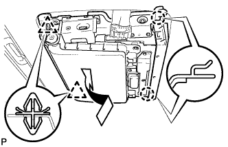
28. INSTALL TELEVISION DISPLAY ASSEMBLY (w/ Rear Seat Entertainment System)

  1. E151790
    Engage the 2 claws and the 2 clips.

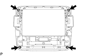
  1. E150582
    Install the television display with the 4 bolts.

    HINT:
    Tighten the bolts in the order shown in the illustration.

  1. Connect the connector.


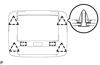
29. INSTALL TELEVISION BASE (w/ Rear Seat Entertainment System)

  1. E150581E01
    Engage the 2 guides and 4 clips and install the television base.


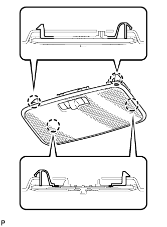
30. INSTALL NO. 2 ROOM LIGHT ASSEMBLY

  1. B139564
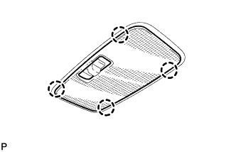
    Engage the 4 claws and install the lens cover.

  1. B139562
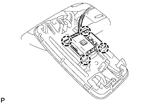
    Engage the 4 claws and install the room light switch base to the No. 2 room light assembly.

  1. B160475
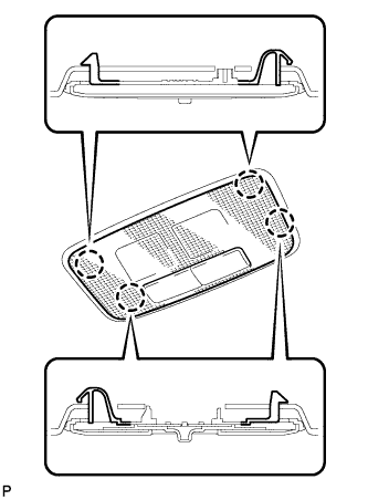
    Engage the 4 claws and install the No. 2 room light assembly.


31. INSTALL NO. 1 ROOM LIGHT ASSEMBLY (for Standard)

  1. B139564
    Engage the 4 claws and install the lens cover.

  1. B139562
    Engage the 4 claws and install the room light switch base to the No. 1 room light assembly.

  1. B160475
    Engage the 4 claws and install the No. 1 room light assembly.


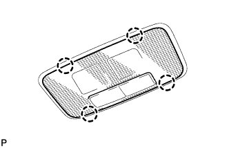
32. INSTALL NO. 1 ROOM LIGHT ASSEMBLY (for Independent Type)

  1. B173253
    Engage the 4 claws and install the lens cover.

  1. B173256
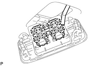
    Engage the 8 claws and install the room light switch base to the No. 1 room light assembly.

  1. B173255
    Engage the 4 claws and install the No. 1 room light assembly.


33. INSTALL INNER REAR VIEW MIRROR STAY HOLDER COVER (w/ EC Mirror)

  1. B175049
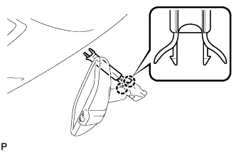
    Engage the 2 claws and install the inner rear view mirror stay holder cover.

  1. B175050E01
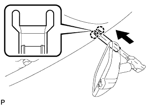
    Engage the 2 claws and install the inner rear view mirror stay holder cover as shown in the illustration.


34. INSTALL VISOR ASSEMBLY LH

  1. B173261
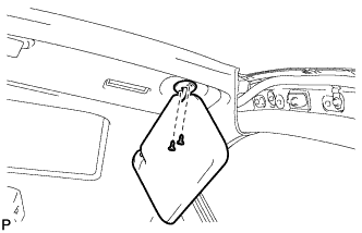
    Install the visor assembly LH with the 2 screws.


35. INSTALL VISOR BRACKET COVER (for LH Side)

  1. B139566
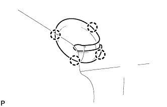
    Engage the 4 claws and install the visor bracket cover.


36. INSTALL VISOR ASSEMBLY RH

HINT:
Use the same procedure for the RH side and the LH side.


37. INSTALL VISOR BRACKET COVER (for RH Side)

HINT:
Use the same procedure for the RH side and the LH side.


38. INSTALL ROOF CONSOLE BOX ASSEMBLY

  1. B173251
    Connect the connector.

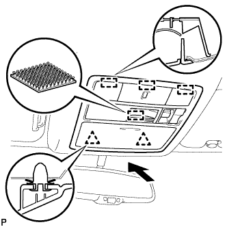
  1. Engage the 3 guides, 2 clips and fastener, and install the roof console box assembly.


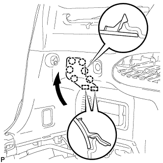
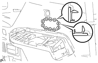
39. INSTALL ROOF SIDE INNER GARNISH ASSEMBLY LH (w/o Power Back Door)

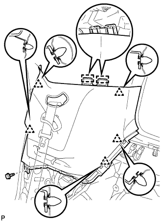
  1. w/ Rear No. 2 Seat:

    1. B173267
      Engage the 2 guides and 5 clips.

    2. Install the roof side inner garnish assembly LH with the bolt.

    3. B175157
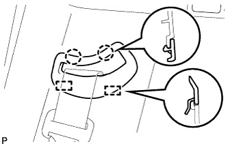
      Engage the 2 guides and 2 claws, and install the No. 2 seat outer belt guide.

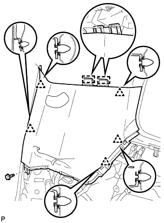
  1. w/o Rear No. 2 Seat:

    1. B173268
      Engage the 2 guides and 5 clips.

    2. Install the roof side inner garnish assembly LH with the bolt.


40. INSTALL ROOF SIDE INNER GARNISH ASSEMBLY LH (w/ Power Back Door)

  1. w/ Rear No. 2 Seat:

    1. B173265
      Engage the 2 guides and 5 clips.

    2. Install the roof side inner garnish assembly LH with the bolt.

    3. B175157
      Engage the 2 guides and 2 claws, and install the No. 2 seat outer belt guide.

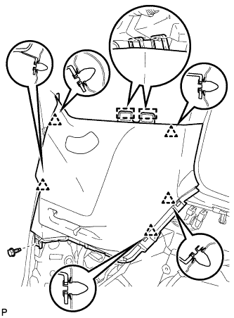
  1. w/o Rear No. 2 Seat:

    1. B173266
      Engage the 2 guides and 5 clips.

    2. Install the roof side inner garnish assembly LH with the bolt.


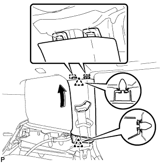
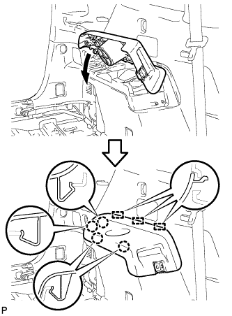
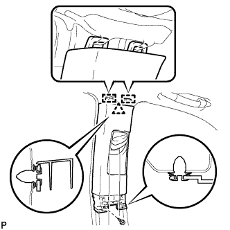
41. INSTALL QUARTER PILLAR GARNISH LH

  1. B173264
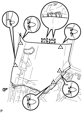
    Engage the 2 guides and the 2 clips, and install the quarter pillar garnish LH as shown in the illustration.

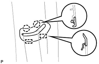
  1. B175156
    Engage the 2 guides and the 2 claws, and install the No. 1 seat outer belt guide.


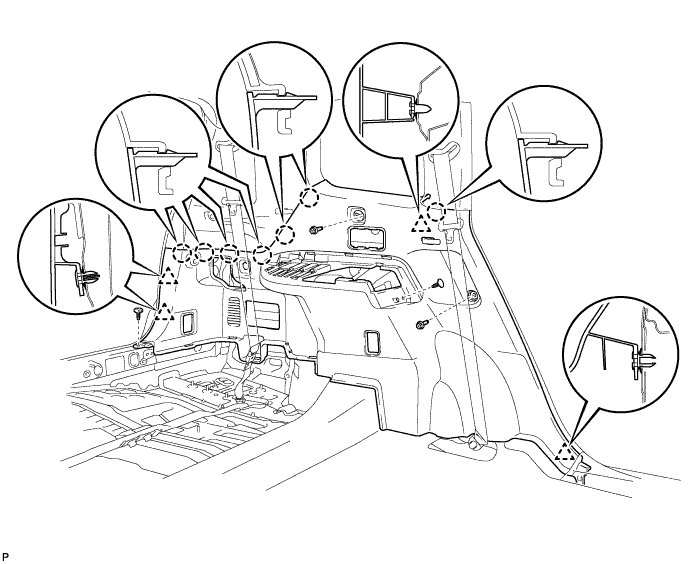
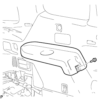
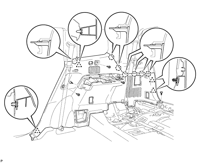
42. INSTALL DECK TRIM SIDE PANEL ASSEMBLY LH
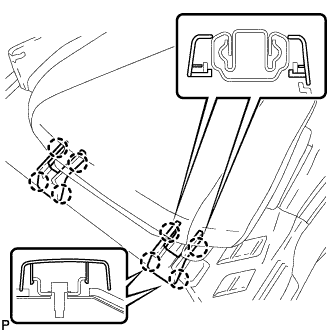
  1. Engage the 4 clips and 7 claws.

  1. Install the 2 clips.

  1. Install the deck trim side panel assembly LH with the 2 bolts.

    B173613


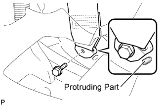
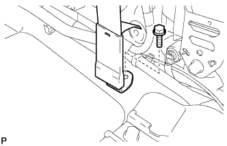
43. CONNECT REAR NO. 1 SEAT OUTER BELT ASSEMBLY LH

  1. B170934E01
    Connect the floor anchor end of the rear No. 1 seat outer belt assembly and install the bolt.

    Torque:
    42 N*m{ 428 kgf*cm , 31 ft.*lbf }

    NOTICE:
    Do not allow the anchor part of the rear No. 1 seat outer belt assembly to overlap the protruding part of the floor panel.


44. INSTALL FRONT DECK SIDE TRIM COVER LH

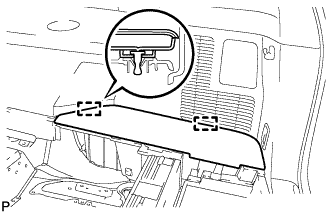
  1. B175145
    Engage the 4 claws and install the 2 front deck side trim covers LH.


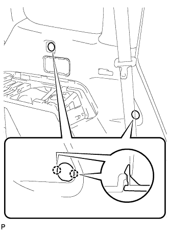
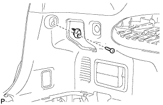
45. INSTALL NO. 2 DECK SIDE TRIM HOOK

  1. B173612
    Install the No. 2 deck side trim hook with the screw.


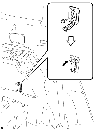
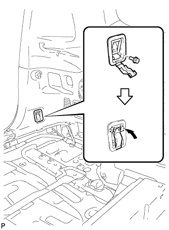
46. INSTALL ROPE HOOK ASSEMBLY (for LH Side)

  1. B173599
    for Front Side:

    1. Install the rope hook assembly with the bolt.

      Torque:
      6.5 N*m{ 66 kgf*cm , 58 in.*lbf }

    2. Engage the 2 claws.

  1. B173601
    for Rear Side:

    1. Install the rope hook assembly with the bolt.

      Torque:
      6.5 N*m{ 66 kgf*cm , 58 in.*lbf }

    2. Engage the 2 claws.


47. INSTALL REAR DECK TRIM COVER (w/o Remote Folding Function)

  1. B173602
    Engage the 10 claws to install the rear deck trim cover.


48. INSTALL RECLINING REMOTE CONTROL LEVER BEZEL LH (w/ Remote Folding Function)

  1. B173603
    Engage the 5 claws to install the reclining remote control lever bezel LH.


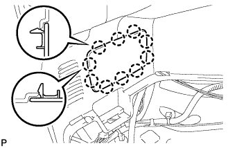
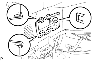
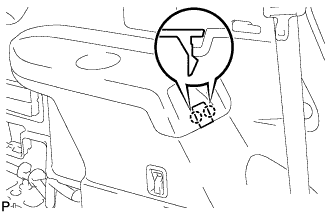
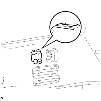
49. INSTALL REAR POWER OUTLET SOCKET COVER

  1. E151328
    Engage the 2 claws and install the rear power outlet socket cover.


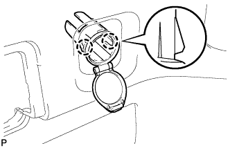
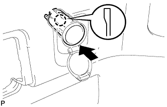
50. INSTALL REAR POWER POINT SOCKET ASSEMBLY

  1. E151490
    Engage the claw and install the rear power point socket assembly.

  1. Connect the connector.


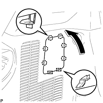
51. INSTALL REAR COMBINATION LIGHT SERVICE COVER LH

  1. B175146
    Engage the 2 guides and 6 claws, and install the rear combination light service cover LH.


52. INSTALL SIDE TRIM COVER LH

  1. B173597
    Engage the 10 claws and install the side trim cover LH.


53. INSTALL DECK SIDE TRIM LH

  1. B173624
    Engage the 3 guides and 4 claws as shown in the illustration.

  1. B173596
    Install the deck side trim LH with the bolt.


54. INSTALL DECK SIDE TRIM COVER NO.2

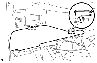
  1. B175144
    Engage the 2 claws and install the deck side trim cover LH.


55. INSTALL ROOF SIDE INNER GARNISH ASSEMBLY RH (w/o Rear No. 2 Seat)

HINT:
Use the same procedure for the RH side and the LH side.


56. INSTALL ROOF SIDE INNER GARNISH ASSEMBLY RH (w/ Rear No. 2 Seat)

HINT:
Use the same procedure for the RH side and the LH side.


57. INSTALL QUARTER PILLAR GARNISH RH

HINT:
Use the same procedure for the RH side and the LH side.


58. INSTALL DECK TRIM SIDE PANEL ASSEMBLY RH
  1. Engage the 4 clips and 7 claws.

  1. Install the 2 clips.

  1. Install the deck trim side panel assembly RH with the 3 bolts.

    B173622


59. CONNECT REAR NO. 1 SEAT OUTER BELT ASSEMBLY RH

HINT:
Use the same procedure for the RH side and the LH side.


60. INSTALL FRONT DECK SIDE TRIM COVER RH

HINT:
Use the same procedure for the RH side and the LH side.


61. INSTALL NO. 1 LUGGAGE COMPARTMENT TRIM HOOK

HINT:
Use the same procedure for the No. 1 luggage compartment trim hook and the No. 2 deck side trim hook.


62. INSTALL ROPE HOOK ASSEMBLY (for RH Side)

HINT:
Use the same procedure for the RH side and the LH side.


63. INSTALL REAR COMBINATION LIGHT SERVICE COVER RH

  1. B173619
    Engage the 2 guides and 6 claws, and install the rear combination light service cover RH.


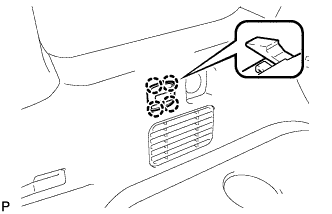
64. INSTALL REAR ROOM TEMPERATURE SENSOR (w/ Rear Automatic Air Conditioning System)
  1. Connect the connector.

  1. E150364
    Engage the 4 claws and install the rear room temperature sensor.


65. INSTALL SIDE TRIM COVER RH (w/o Rear Automatic Air Conditioning System)

  1. B173610
    Engage the 4 claws, and install the side trim cover RH.


66. INSTALL DECK SIDE TRIM RH

HINT:
Use the same procedure for the RH side and the LH side.


67. INSTALL DECK SIDE TRIM COVER NO.1

HINT:
Use the same procedure for the RH side and the LH side.


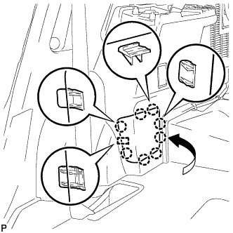
68. INSTALL REAR SEAT SIDE GARNISH CAP (w/o Rear Air Conditioning System)

  1. B173615
    Engage the guide and 8 claws, and install the rear seat side garnish cap.


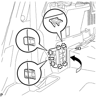
69. INSTALL REAR SEAT SIDE GARNISH CAP (w/ Rear Air Conditioning System)

  1. B173617
    Engage the guide and 6 claws.

  1. Install the rear seat side garnish cap with the screw.


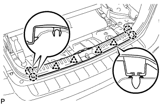
70. INSTALL REAR FLOOR FINISH PLATE

  1. B173609
    Engage the 4 clips and 4 claws, and install the rear floor finish plate.


71. INSTALL REAR NO. 2 SEAT ASSEMBLY (w/ Rear No. 2 Seat)

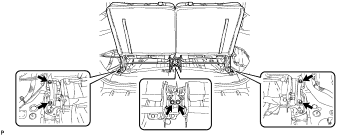
  1. Install the 6 bolts on the rear of the seat.

    B260174

    Torque:
    37 N*m{ 377 kgf*cm , 27 ft.*lbf }

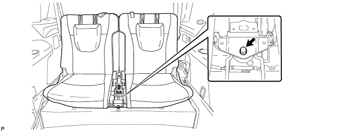
  1. Install the rear No. 2 seat assembly with the bolt.

    B260173

    Torque:
    37 N*m{ 377 kgf*cm , 27 ft.*lbf }


72. INSTALL CENTER SEAT CUSHION COVER SUB-ASSEMBLY (w/ Rear No. 2 Seat)

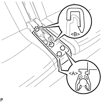
  1. B260172E01
    Engage the 2 claws <B>.

  1. Engage the 2 claws <A> to install the center seat cushion cover sub-assembly.


73. CONNECT REAR NO. 2 SEAT OUTER BELT ASSEMBLY LH (w/ Rear No. 2 Seat)

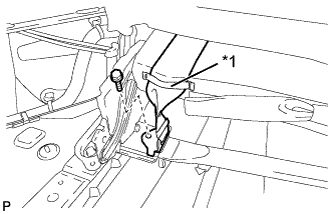
  1. B256544E01
    Route the rear No. 2 seat outer belt assembly LH through the rubber band as shown in the illustration.
    Text in Illustration 
    *1
    Rubber Band

  1. Install the rear No. 2 seat outer belt assembly LH with the bolt.

    Torque:
    42 N*m{ 428 kgf*cm , 31 ft.*lbf }

    NOTICE:
    After installing the belt, check that it is not twisted.


74. CONNECT REAR NO. 2 SEAT OUTER BELT ASSEMBLY RH (w/ Rear No. 2 Seat)

HINT:
Use the same procedure as for the LH side.


75. INSTALL NO. 1 DECK BOARD (w/o Rear No. 2 Seat)

  1. B178559
    Engage the 5 clips and install the rear floor board spacer to the No. 1 deck board.


76. INSTALL NO. 1 DECK BOARD (w/ Rear No. 2 Seat)

  1. B259820
    Engage the 3 clips and install the No. 1 deck board.


77. INSTALL NO. 2 DECK BOARD (w/ Rear No. 2 Seat)

  1. B259819
    Engage the 3 clips and install the No. 2 deck board.


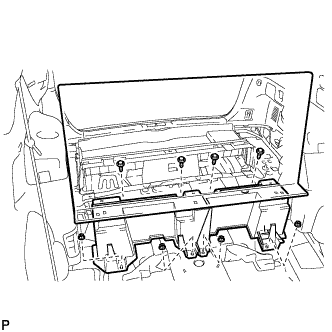
78. INSTALL REAR DECK FLOOR BOX (w/o Rear No. 2 Seat)

  1. B173679
    Install the rear deck floor box with the 2 nuts.


79. INSTALL DECK FLOOR BOARD ASSEMBLY (w/o Rear No. 2 Seat)

  1. B178560
    Install the 2 nuts and deck floor board assembly.

  1. Engage the 3 claws.


80. INSTALL REAR MAT

  1. B173249
    Install the rear mat.


81. INSTALL DECK FLOOR BOARD ASSEMBLY (w/ Rear No. 2 Seat)

  1. B260042
    Install the rear deck floor board assembly with the 4 nuts and 4 bolts.


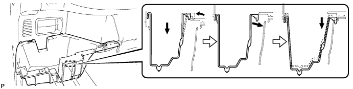
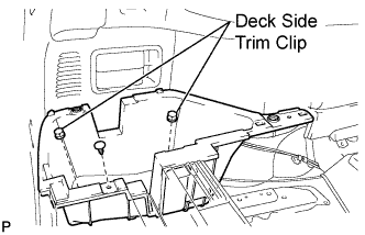
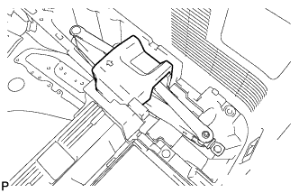
82. INSTALL DECK SIDE TRIM BOX LH

  1. Install the deck side trim box LH as shown in the illustration.

    B178555

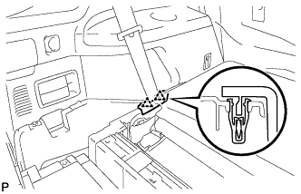
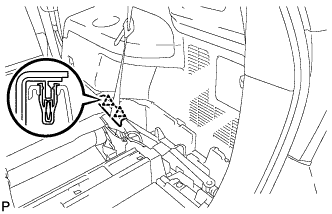
  1. B173243E01
    Install the 2 deck side trim clips and clip.


83. INSTALL REAR SEAT SIDE COVER LH (w/ Rear No. 2 Seat)

  1. B173607
    Engage the 2 clips and install the rear seat side cover LH.


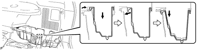
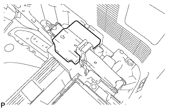
84. INSTALL DECK SIDE TRIM BOX RH

  1. Install the deck side trim box RH as shown in the illustration.

    B178553

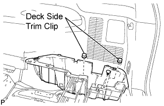
  1. B173247E01
    Install the 2 deck side trim clips and clip.


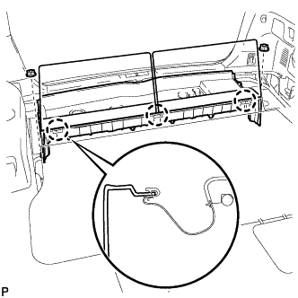
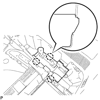
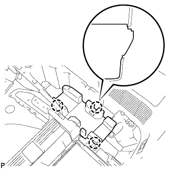
85. INSTALL JACK CARRIER ASSEMBLY (for LHD)

  1. B178549
    Engage the 3 claws, and install the jack carrier assembly.


86. INSTALL JACK CARRIER ASSEMBLY (for RHD)

  1. B179786
    Engage the 3 claws, and install the jack carrier assembly.


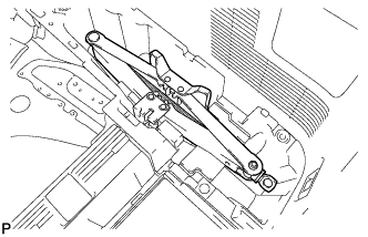
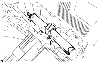
87. INSTALL JACK ASSEMBLY (for LHD)

  1. B173245
    Install the jack assembly.


88. INSTALL JACK ASSEMBLY (for RHD)

  1. B178566
    Install the jack assembly.


89. INSTALL JACK CARRIER CUSHION (for LHD)

  1. B178550
    Install the jack carrier cushion.


90. INSTALL JACK CARRIER CUSHION (for RHD)

  1. B178551
    Install the jack carrier cushion.


91. INSTALL JACK CARRIER SUPPORT

92. INSTALL REAR SEAT SIDE COVER RH (w/ Rear No. 2 Seat)

  1. B173608
    Engage the 2 clips and install the rear seat side cover RH.


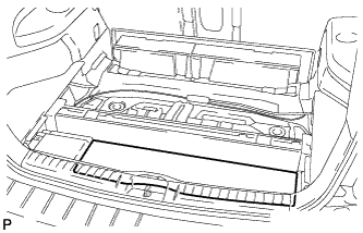
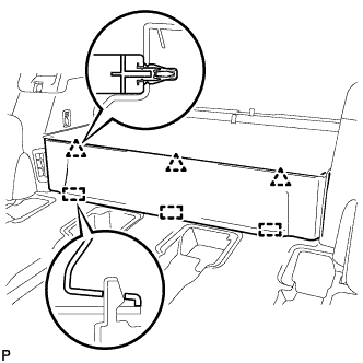
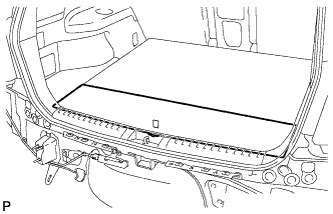
93. INSTALL REAR NO. 1 FLOOR BOARD (w/o Rear No. 2 Seat)

  1. B175152
    Engage the 3 guides and 3 clips and install the rear No. 1 floor board.


94. INSTALL TONNEAU COVER ASSEMBLY (w/ Tonneau Cover)
  1. Install the tonneau cover assembly.


95. INSTALL NO. 2 DECK BOARD SUB-ASSEMBLY

  1. B173244
    Engage the 2 guides and install the No. 2 deck board sub-assembly.


96. INSTALL NO. 3 DECK BOARD SUB-ASSEMBLY

  1. B173242
    Engage the 2 guides and install the No. 3 deck board sub-assembly.


97. INSTALL DECK BOARD ASSEMBLY

  1. B173240
    Install the deck board assembly.


98. INSTALL CENTER PILLAR GARNISH LH

  1. B173229
    Engage the 2 guides and clip.

  1. Install the center pillar garnish LH with the clip and screw.


99. CONNECT FRONT SEAT OUTER BELT ASSEMBLY LH

  1. B170910
    Install the floor end of the front seat outer belt assembly with the bolt.

    Torque:
    42 N*m{ 428 kgf*cm , 31 ft.*lbf }

  1. Check if the ELR locks.

    NOTICE:
    The check should be performed with the outer belt assembly installed.


    1. With the belt assembly installed, check that the belt locks when it is pulled out quickly.


100. INSTALL LOWER CENTER PILLAR GARNISH LH

  1. B173231
    Engage the 2 claws and 2 clips, and install the lower center pillar garnish LH.


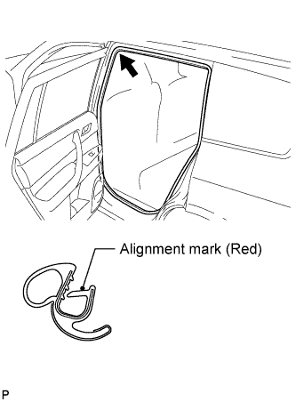
101. INSTALL REAR DOOR OPENING TRIM WEATHERSTRIP LH

  1. B173233E01
    Align the alignment mark (red) on the weatherstrip with the protruding portion on the body indicated by the arrow in the illustration, and install the rear door opening trim weatherstrip LH.

    NOTICE:
    After installation, check that the corners fit correctly.


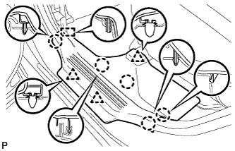
102. INSTALL REAR DOOR SCUFF PLATE LH

  1. B173228
    Engage the guide, 3 clips and 5 claws, and install the rear door scuff plate LH.


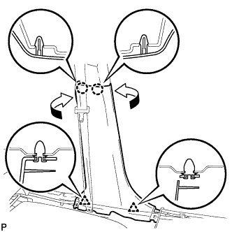
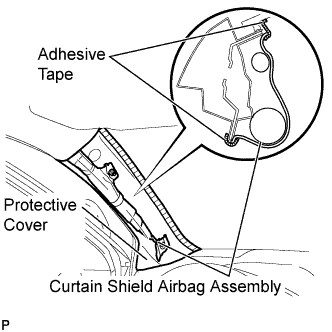
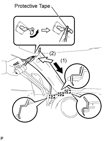
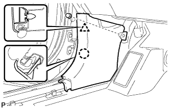
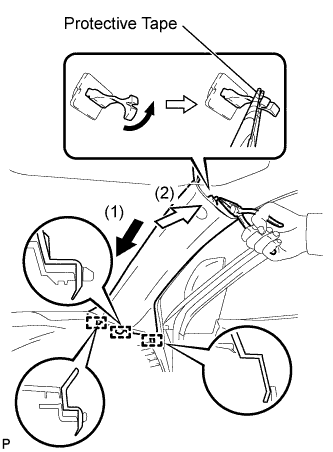
103. INSTALL FRONT PILLAR GARNISH LH

  1. B173226E01
    Remove the protective cover.

  1. B260163E01
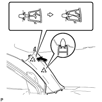
    Make sure that the front pillar garnish clip is not damaged.

    NOTICE:
    1. If there is any damage, replace the garnish clip with a new one.
    2. When a garnish clip is being replaced, make sure to install it in the direction shown in the illustration.

  1. Engage the 3 guides.

  1. Turn the end of the front pillar garnish clip 90° with needle-nosed pliers and install it to the front pillar garnish LH.

    HINT:
    Tape the tips of the needle-nosed pliers before use.

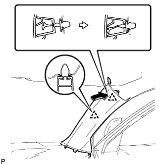
  1. B260164
    Engage the 2 clips to install the front pillar garnish LH.


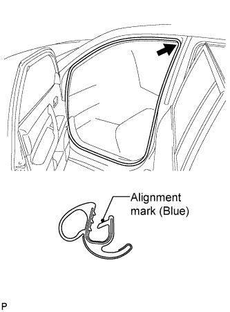
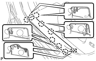
104. INSTALL FRONT DOOR OPENING TRIM WEATHERSTRIP LH

  1. B173235E01
    Align the alignment mark (blue) on the weatherstrip with the protruding portion on the body indicated by the arrow in the illustration, and install the front door opening trim weatherstrip LH.

    NOTICE:
    After installation, check that the corners fit correctly.


105. INSTALL COWL SIDE TRIM SUB-ASSEMBLY LH

  1. B173227
    Engage the claw and clip, install the cowl side trim sub-assembly LH.

  1. Install the clip.


106. INSTALL FRONT DOOR SCUFF PLATE LH

  1. B173224
    Engage the guide and 8 claws, and install the front door scuff plate LH.


107. INSTALL CENTER PILLAR GARNISH RH

HINT:
Use the same procedure for the RH side and the LH side.


108. CONNECT FRONT SEAT OUTER BELT ASSEMBLY RH

HINT:
Use the same procedure for the RH side and the LH side.


109. INSTALL LOWER CENTER PILLAR GARNISH RH

HINT:
Use the same procedure for the RH side and the LH side.


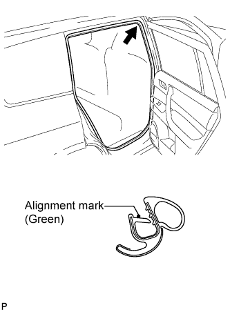
110. INSTALL REAR DOOR OPENING TRIM WEATHERSTRIP RH

  1. B173237E01
    Align the alignment mark (green) on the weatherstrip with the protruding portion on the body indicated by the arrow in the illustration, and install the rear door opening trim weatherstrip RH.

    NOTICE:
    After installation, check that the corners fit correctly.


111. INSTALL REAR DOOR SCUFF PLATE RH

HINT:
Use the same procedure for the RH side and the LH side.


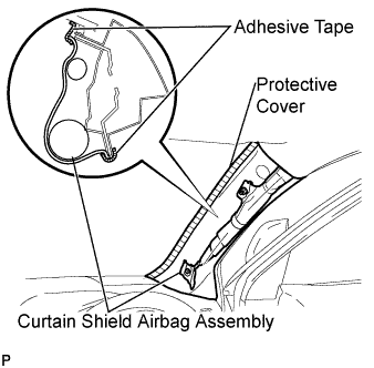
112. INSTALL FRONT PILLAR GARNISH RH

  1. B173685E01
    Remove the protective cover.

  1. B260165E01
    Make sure that the front pillar garnish clip is not damaged.

    NOTICE:
    1. If there is any damage, replace the garnish clip with a new one.
    2. When a garnish clip is being replaced, make sure to install it in the direction shown in the illustration.

  1. Engage the 3 guides.

  1. Turn the end of the front pillar garnish clip 90° with needle-nosed pliers and install it to the front pillar garnish RH.

    HINT:
    Tape the tips of the needle-nosed pliers before use.

  1. B260166
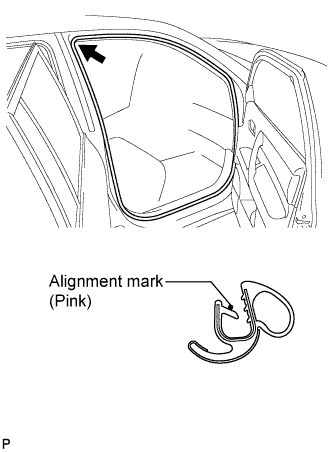
    Engage the 2 clips to install the front pillar garnish RH.


113. INSTALL FRONT DOOR OPENING TRIM WEATHERSTRIP RH

  1. B173239E01
    Align the alignment mark (pink) on the weatherstrip with the protruding portion on the body indicated by the arrow in the illustration, and install the front door opening trim weatherstrip RH.

    NOTICE:
    After installation, check that the corners fit correctly.


114. INSTALL COWL SIDE TRIM SUB-ASSEMBLY RH

HINT:
Use the same procedure for the RH side and the LH side.


115. INSTALL FRONT DOOR SCUFF PLATE RH

HINT:
Use the same procedure for the RH side and the LH side.


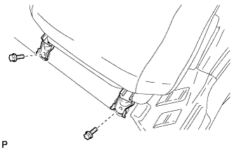
116. INSTALL REAR NO. 1 SEAT ASSEMBLY LH

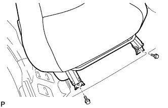
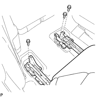
  1. B173778
    Temporarily install the 2 bolts on the front side of the seat.

  1. B173780
    Temporarily install the 3 bolts on the rear side of the seat.

  1. Install the rear No. 1 seat assembly with the 5 bolts.

    Torque:
    37 N*m{ 377 kgf*cm , 27 ft.*lbf }


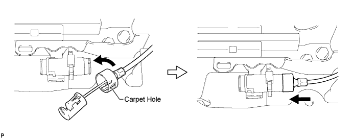
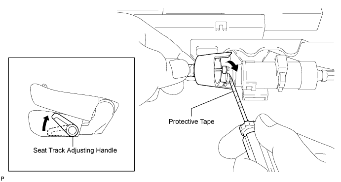
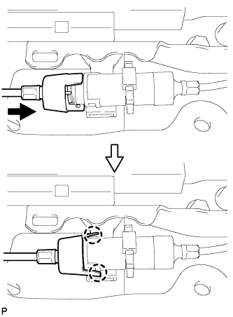
117. CONNECT REAR NO. 1 SEAT LOCK CABLE ASSEMBLY LH (w/ Remote Folding Function)

  1. Remove the rear seat reclining control cable from the carpet hole.

    B180395E01

  1. Connect the rear seat reclining control cable as shown in the illustration.

  1. Connect the rear No. 1 seat lock cable assembly as shown in the illustration.

    B173771E01

  1. B174591
    Engage the 2 claws and connect the rear No. 1 seat lock cable assembly as shown in the illustration.

  1. Return the seatback to the upright position.

  1. Pull up the adjuster's lock piece to lock it as shown in the illustration.

    B180389E01

    NOTICE:
    When pressing the lock piece, make sure the adjuster's spring is not compress.


118. INSPECT REAR SEAT SLIDE ADJUSTER LOCK (for LH Side)
  1. Check that the left and right adjusters lock simultaneously when sliding the seat.

  1. If the left and right adjusters do not lock simultaneously, adjust by loosening the bolts securing the seat.


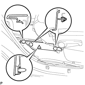
119. INSTALL REAR SEAT LEG SIDE COVER LH

  1. B173779
    Engage the clip.

  1. Engage the 3 claws and install the rear seat leg side cover.


120. INSTALL REAR INNER TRACK BRACKET COVER LH

  1. B173777
    Engage the 4 claws and install the rear inner track bracket cover.


121. INSTALL REAR OUTER TRACK BRACKET COVER LH

  1. B173776
    Engage the 4 claws and install the rear outer track bracket cover.


122. INSTALL REAR SEAT TRACK BRACKET COVER LH

  1. B173775
    Engage the 8 claws and install the 2 rear seat track bracket covers.


123. INSTALL REAR SEAT HEADREST ASSEMBLY (for LH Side)

124. INSTALL REAR CENTER SEAT ASSEMBLY

125. INSTALL REAR NO. 1 SEAT ASSEMBLY RH

  1. B173764
    Temporarily install the 2 bolts on the front side of the seat.

  1. B173774
    Temporarily Install the 3 bolts on the rear side of the seat.

  1. Install the rear No. 1 seat assembly with the 5 bolts.
    Torque:
    37 N*m{ 377 kgf*cm , 27 ft.*lbf }


126. CONNECT REAR NO. 1 SEAT LOCK CABLE ASSEMBLY RH (w/ Remote Folding Function)

HINT:
Use the same procedure for the RH side and the LH side.


127. INSPECT REAR SEAT SLIDE ADJUSTER LOCK (for RH Side)
  1. Check that the left and right adjusters lock simultaneously when sliding the seat.

  1. If the left and right adjusters do not lock simultaneously, adjust by loosening the bolts securing the seat.


128. INSTALL REAR SEAT LEG SIDE COVER RH

  1. B173765
    Engage the clip.

  1. Engage the 3 claws and install the rear seat leg side cover.


129. INSTALL REAR INNER TRACK BRACKET COVER RH

  1. B173761
    Engage the 4 claws and install the rear inner track bracket cover.


130. INSTALL REAR OUTER TRACK BRACKET COVER RH

  1. B173763
    Engage the 4 claws and install the rear outer track bracket cover.


131. INSTALL REAR SEAT TRACK BRACKET COVER RH

  1. B173760
    Engage the 8 claws and install the 2 seat track bracket covers.

132. INSTALL REAR SEAT HEADREST ASSEMBLY (for RH Side)
← INSTALLATION (Aug 2008 – Jun 2010)COMPONENTS (May 2007 – Jun 2010) →