1.
INSTALL REAR ROOF SIDE RAIL PAD LH (w/ Sliding Roof)
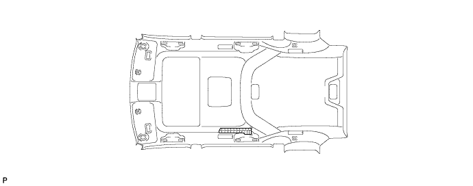
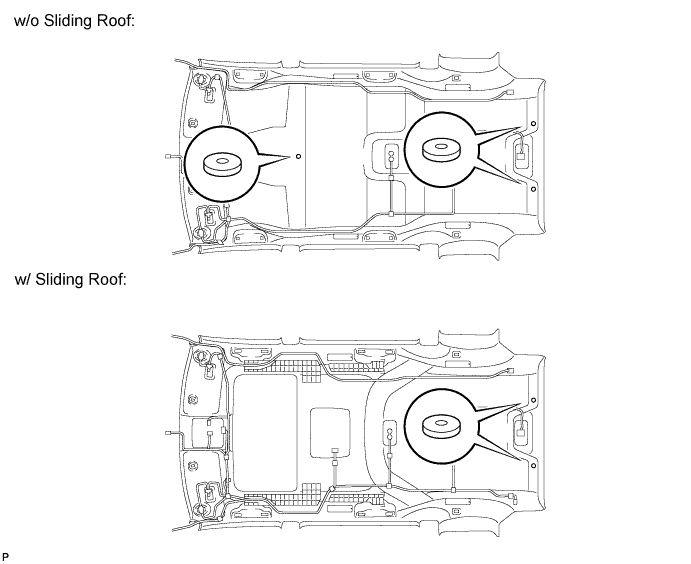
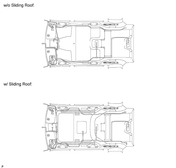
Align the markings on the roof headlining assembly with the rear roof side rail pad LH and install the pad using hot melt glue as shown in the illustration.
2.
INSTALL REAR ROOF SIDE RAIL PAD RH (w/ Sliding Roof)
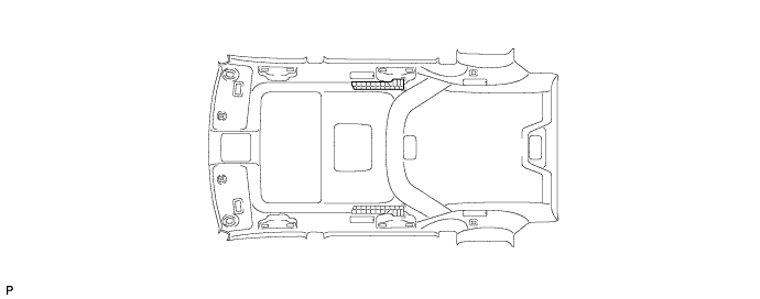
Align the markings on the roof headlining assembly with the rear roof side rail pad RH and install the pad using hot melt glue as shown in the illustration.
3.
INSTALL ROOF SIDE RAIL GARNISH PAD LH (w/ Sliding Roof)
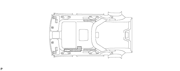
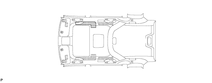
Align the markings on the roof headlining assembly with the roof side rail garnish pad LH and install the pad using hot melt glue as shown in the illustration.
4.
INSTALL ROOF SIDE RAIL GARNISH PAD RH (w/ Sliding Roof)
Align the markings on the roof headlining assembly with the roof side rail garnish pad RH and install the pad using hot melt glue as shown in the illustration.
5.
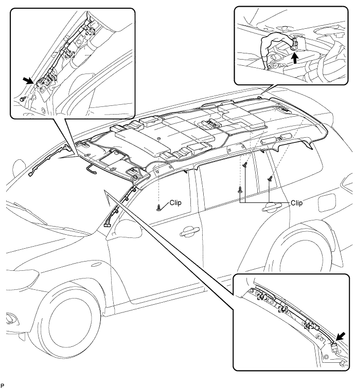
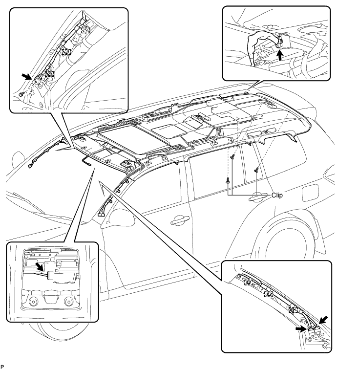
INSTALL NO. 2 ANTENNA CORD SUB-ASSEMBLY
HINT:
The double-sided tape and tape are not available as supply parts. If these tapes still have enough adhesion to secure the roof headlining and antenna cord, reuse the tapes. If the roof headlining has been replaced with a new one, or if the tape and/or the double-sided tape is no longer sticky, apply new tape following the procedures below.
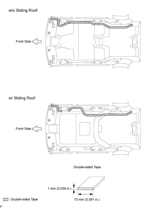
Apply new double-sided tape.
Remove the double-sided tape from the roof headlining assembly.
Peel off the appropriate amount of new double-sided tape. Be careful not to touch the adhesive surface.
Apply the double-sided tape to the roof headlining while aligning the tape with the markings on the roof headlining assembly.
Peel off the backing sheet from the double-sided tape.
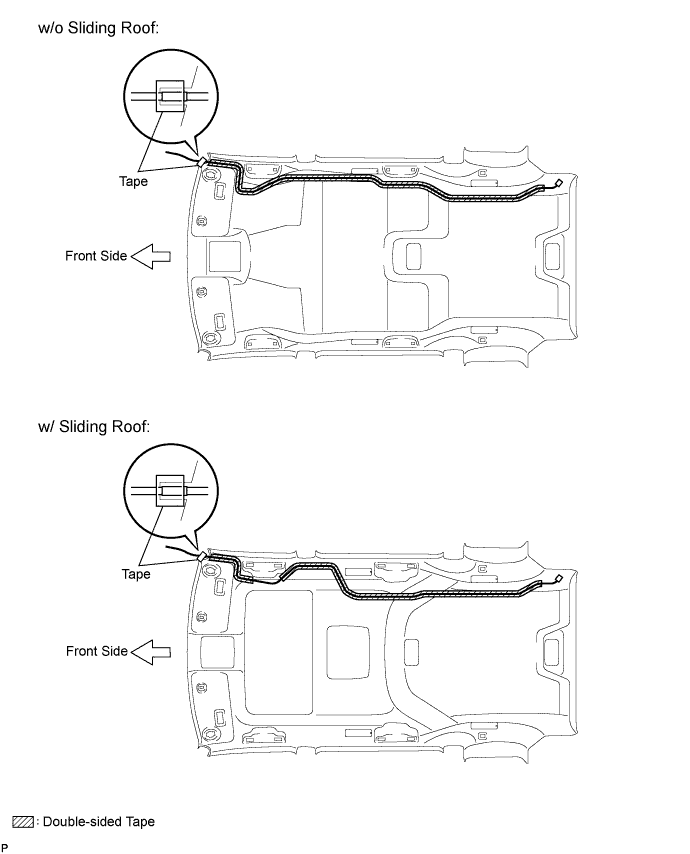
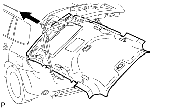
Install the antenna cord to the roof headlining assembly from the front of the vehicle.
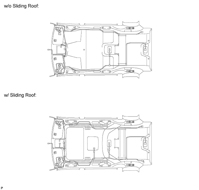
Put the strips of the tape back to the positions shown in the illustration in order to secure the antenna cord to the roof headlining assembly.
HINT:
For the right front corner of the roof headlining assembly, align the marking tape on the antenna cord with the protrusion of the roof headlining, and wrap tape around the antenna cord and roof headlining assembly once or twice to securely hold them.
6.
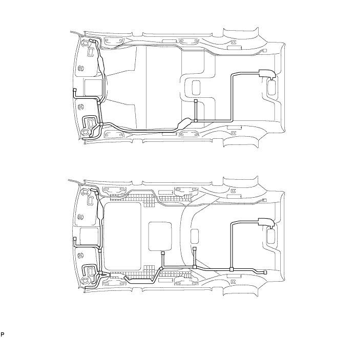
INSTALL NO. 1 ROOF WIRE
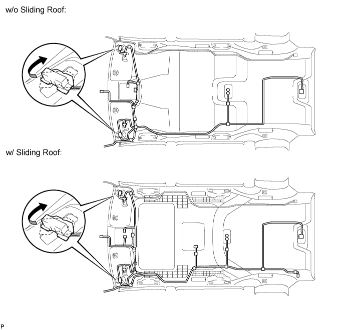
Peel off the release paper from the double-sided tape.
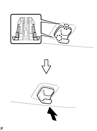
w/ Vanity Light:
Turn the visor connectors clockwise approximately 90° to install the connectors to the roof headlining.
Attach the No. 1 roof wire along the double-sided tape so that the marking surface of the wire harness faces downward.
NOTICE:
Securely attach the No. 1 roof wire. Failure to do so may cause abnormal noise.
7.
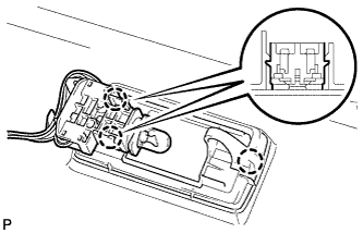
INSTALL NO. 1 AIR OUTLET REGISTER ASSEMBLY (w/ Rear Air Conditioning System)
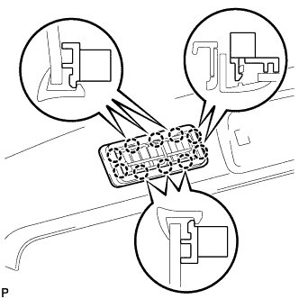
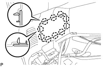
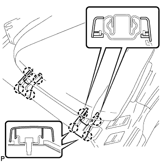
Engage the 10 claws and install the No. 1 air outlet register assembly into the roof side air outlet register.
8.
INSTALL NO. 2 ROOF HEADLINING SUPPORT
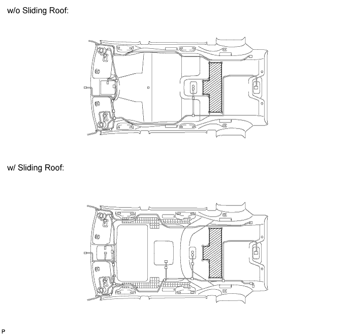
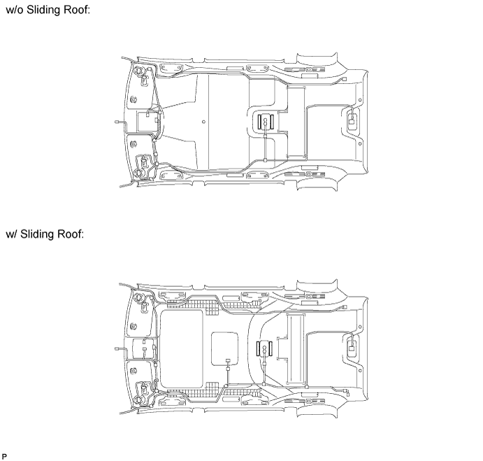
Align the markings on the roof headlining assembly with the No. 2 roof headlining support(s) and install the headlining supports using hot melt glue as shown in the illustration.
9.
INSTALL NO. 4 ROOF SILENCER PAD
Align the markings on the roof headlining assembly with the No. 4 roof silencer pad and install the silencer pad using hot melt glue as shown in the illustration.
10.
INSTALL NO. 2 ROOF HEADLINING PAD
Align the markings on the roof headlining assembly with the 2 No. 2 roof headlining pads and install the pads using hot melt glue as shown in the illustration.
11.
INSTALL ROOF HEADLINING PAD
Align the markings on the roof headlining assembly with the 2 roof headlining pads and install the pads using hot melt glue as shown in the illustration.
12.
INSTALL NO. 1 ROOF HEADLINING SUPPORT
Align the markings on the roof headlining assembly with the 2 No. 1 roof headlining supports and install the headlining supports using hot melt glue as shown in the illustration.
13.
INSTALL NO. 2 ROOF SILENCER PAD (w/o Sliding Roof)
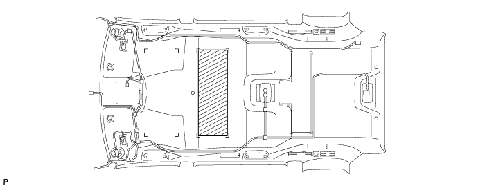
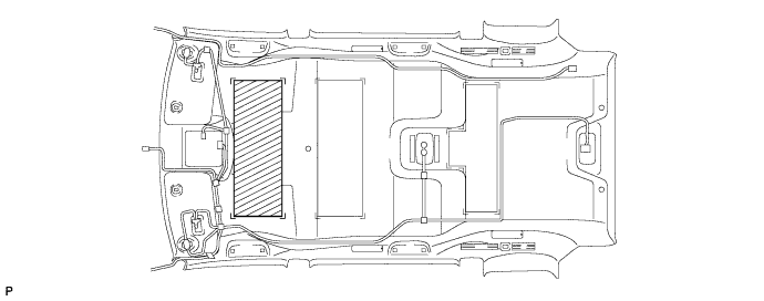
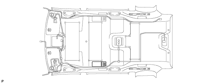
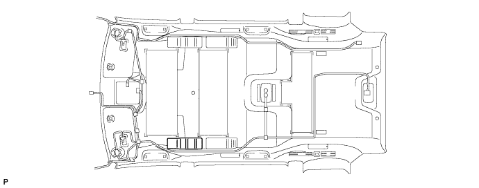
Align the markings on the roof headlining assembly with the No. 2 roof silencer pad and install the silencer pad using hot melt glue as shown in the illustration.
14.
INSTALL NO. 1 ROOF SILENCER PAD (w/o Sliding Roof)
Align the markings on the roof headlining assembly with the No. 1 roof silencer pad and install the silencer pad using hot melt glue as shown in the illustration.
Align the markings on the roof headlining assembly with the rear No. 2 side rail spacer LH and install the spacer using hot melt glue as shown in the illustration.
Use the same procedure for the RH side and the LH side.
17.
INSTALL FRONT SIDE RAIL SPACER LH (w/o Sliding Roof)
Align the markings on the roof headlining assembly with the front side rail spacer LH and install the spacer using hot melt glue as shown in the illustration.
18.
INSTALL FRONT SIDE RAIL SPACER RH (w/o Sliding Roof)
HINT:
Use the same procedure for the RH side and the LH side.
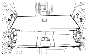
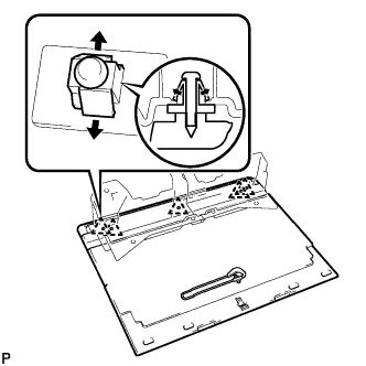
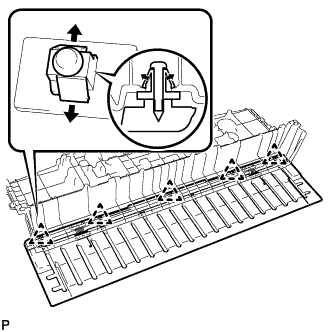
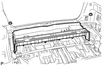
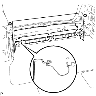
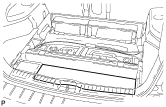
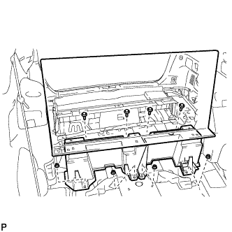
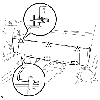
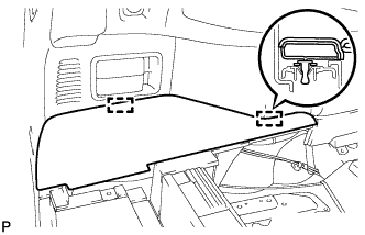
Engage the 2 guides and install the No. 2 deck board sub-assembly.
95.
INSTALL NO. 3 DECK BOARD SUB-ASSEMBLY
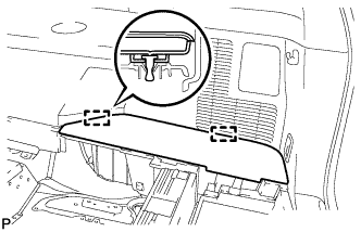
Engage the 2 guides and install the No. 3 deck board sub-assembly.
96.
INSTALL DECK BOARD ASSEMBLY
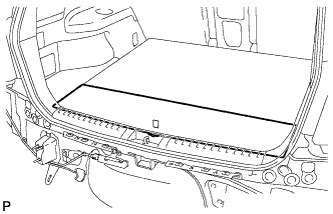
Install the deck board sub-assembly.
97.
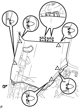
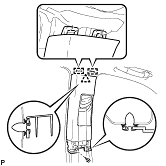
INSTALL CENTER PILLAR GARNISH LH
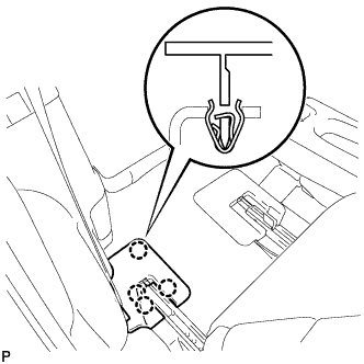
Engage the 2 guides and the clip.
Install the center pillar garnish LH with the clip and screw.
98.
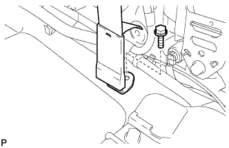
CONNECT FRONT SEAT OUTER BELT ASSEMBLY LH
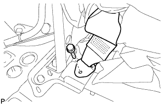
Install the floor end of the front seat outer belt assembly with the bolt.
Torque:
42 N*m{
428 kgf*cm
, 31 ft.*lbf
}
Check if the ELR locks.
NOTICE:
The check should be performed with the outer belt assembly installed.
With the belt assembly installed, check that the belt locks when it is pulled out quickly.
99.
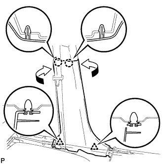
INSTALL LOWER CENTER PILLAR GARNISH LH
Engage the 2 claws and the 2 clips, and install the lower center pillar garnish LH.
100.
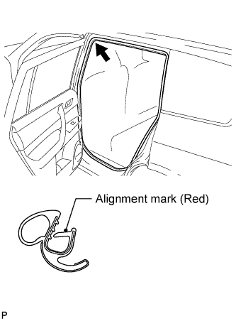
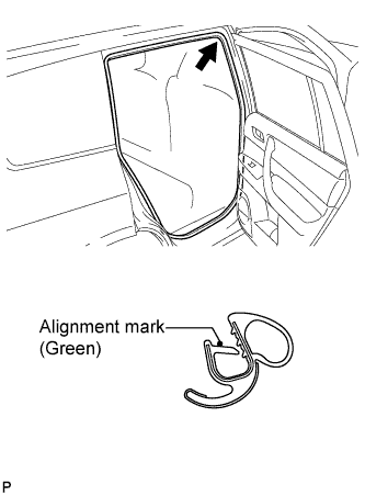
INSTALL REAR DOOR OPENING TRIM WEATHERSTRIP LH
Align the alignment mark (red) on the weatherstrip with the protruding portion on the body indicated by the arrow in the illustration, and install the rear door opening trim weatherstrip LH.
NOTICE:
After installation, check that the corners fit correctly.
101.
INSTALL REAR DOOR SCUFF PLATE LH
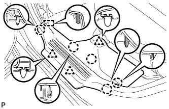
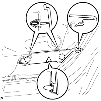
Engage the guide, 3 clips and 5 claws, and install the rear door scuff plate LH.
102.
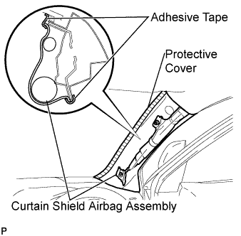
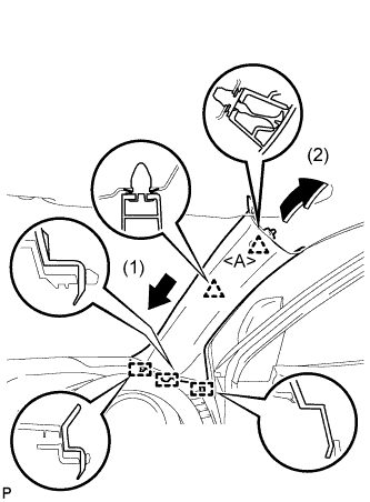
INSTALL FRONT PILLAR GARNISH LH
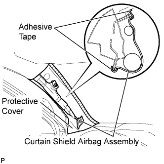
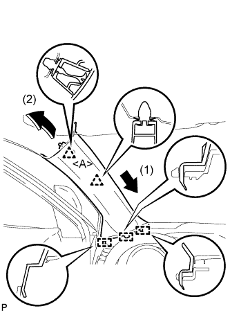
Remove the protective cover.
Install a new clip <A> on the front pillar garnish LH.
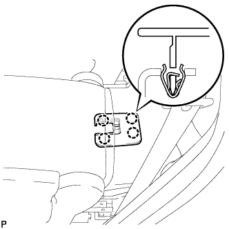
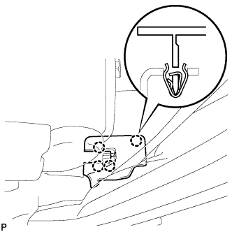
Engage the 3 guides and 2 clips, then install the front pillar garnish LH.
103.
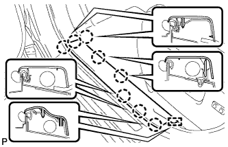
INSTALL FRONT DOOR OPENING TRIM WEATHERSTRIP LH
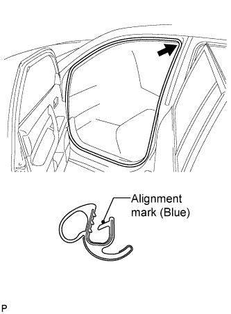
Align the alignment mark (blue) on the weatherstrip with the protruding portion on the body indicated by the arrow in the illustration, and install the front door opening trim weatherstrip LH.
NOTICE:
After installation, check that the corners fit correctly.
104.
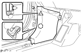
INSTALL COWL SIDE TRIM SUB-ASSEMBLY LH
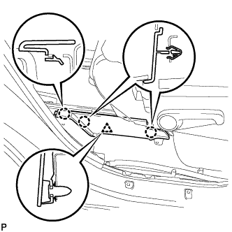
Engage the claw and clip, install the cowl side trim sub-assembly LH.
Install the clip.
105.
INSTALL FRONT DOOR SCUFF PLATE LH
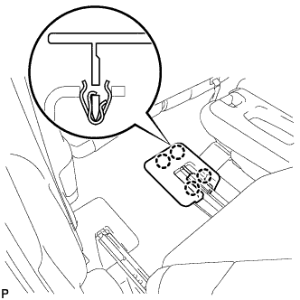
Engage the guide and the 8 claws, and install the front door scuff plate LH.
106.
INSTALL CENTER PILLAR GARNISH RH
HINT:
Use the same procedure for the RH side and the LH side.
107.
CONNECT FRONT SEAT OUTER BELT ASSEMBLY RH
HINT:
Use the same procedure for the RH side and the LH side.
108.
INSTALL LOWER CENTER PILLAR GARNISH RH
HINT:
Use the same procedure for the RH side and the LH side.
109.
INSTALL REAR DOOR OPENING TRIM WEATHERSTRIP RH
Align the alignment mark (green) on the weatherstrip with the protruding portion on the body indicated by the arrow in the illustration, and install the rear door opening trim weatherstrip RH.
NOTICE:
After installation, check that the corners fit correctly.
110.
INSTALL REAR DOOR SCUFF PLATE RH
HINT:
Use the same procedure for the RH side and the LH side.
111.
INSTALL FRONT PILLAR GARNISH RH
Remove the protective cover.
Install a new clip <A> on the front pillar garnish RH.
Engage the 3 guides and 2 clips, then install the front pillar garnish RH.
112.
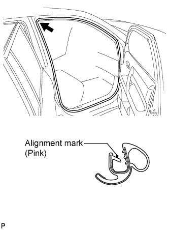
INSTALL FRONT DOOR OPENING TRIM WEATHERSTRIP RH
Align the alignment mark (pink) on the weatherstrip with the protruding portion on the body indicated by the arrow in the illustration, and install the front door opening trim weatherstrip RH.
NOTICE:
After installation, check that the corners fit correctly.
113.
INSTALL COWL SIDE TRIM SUB-ASSEMBLY RH
HINT:
Use the same procedure for the RH side and the LH side.
114.
INSTALL FRONT DOOR SCUFF PLATE RH
HINT:
Use the same procedure for the RH side and the LH side.
115.
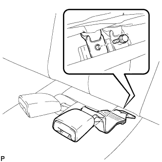
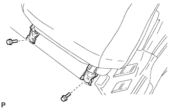
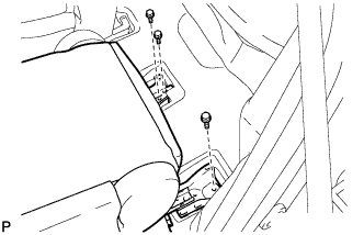
INSTALL REAR NO. 1 SEAT ASSEMBLY LH
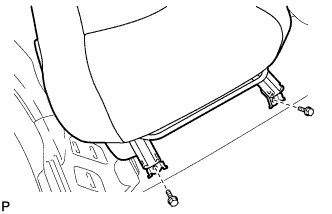
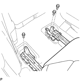
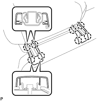
Temporarily install the 2 bolts on the front side of the seat.
Temporarily install the 3 bolts on the rear side of the seat.
Install the rear No. 1 seat assembly with the 5 bolts.