2007-2013 Highlander Kluger · Service Manual HEATER & AIR CONDITIONING SYSTEM

INSTALLATION

Removal / installation · Vehicles built Aug 2008 – Jun 2010

Versions by build date: May 2007 – Jul 2008 Aug 2008 – Jun 2010 from Jul 2010


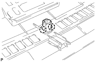
1. INSTALL SOLAR SENSOR

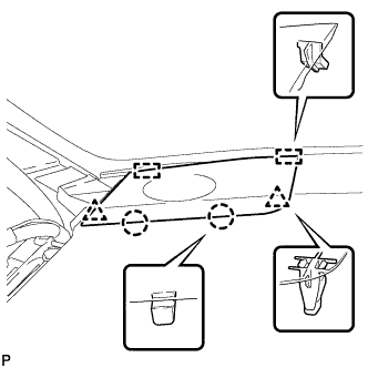
  1. E150082
    Engage the 2 claws and install the solar sensor.

  1. Connect the connector.


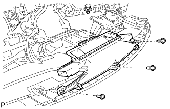
2. INSTALL DEFROSTER NOZZLE ASSEMBLY

  1. B173016
    Install the defroster nozzle assembly with the 3 screws <F> and clip.


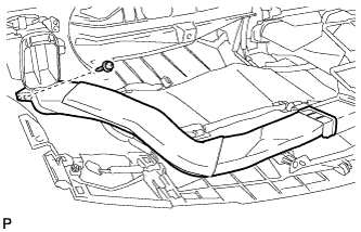
3. INSTALL SIDE NO. 2 DEFROSTER NOZZLE DUCT

  1. B168381
    Install the side No. 2 defroster nozzle duct with the screw <F>.


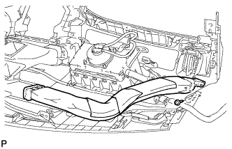
4. INSTALL SIDE NO. 1 DEFROSTER NOZZLE DUCT

  1. B168380
    Install the side No. 1 defroster nozzle duct with the screw <F>.


5. INSTALL NO. 4 HEATER TO REGISTER DUCT

  1. B168379
    Install the No. 4 heater to register duct with the 3 screws <F>.


6. INSTALL NO. 1 HEATER TO REGISTER DUCT

  1. B168378
    Install the No. 1 heater to register duct with the 3 screws <F>.


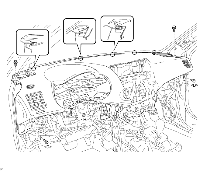
7. INSTALL INSTRUMENT PANEL SAFETY PAD ASSEMBLY (for Pole Antenna Type)
  1. Engage the 5 claws.

    NOTICE:
    Do not allow the wire harness to get caught in the claws.

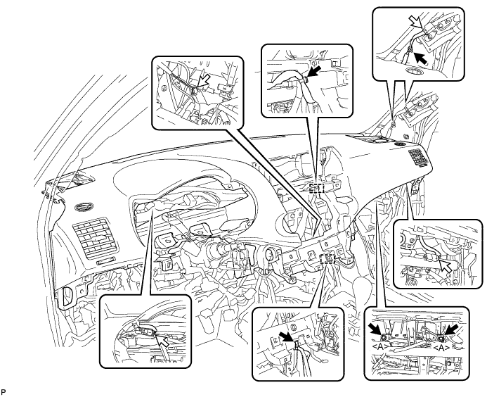
  1. Install the 2 bolts <D> and nut <H>.

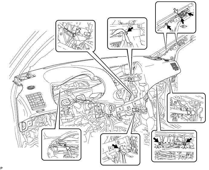
  1. Install the 2 clips.

    B168377E01

  1. Engage each clamp.

  1. Install the 2 passenger airbag bolts <A>.

    Torque:
    20 N*m{ 204 kgf*cm , 15 ft.*lbf }

  1. Install the bolt <E>.

  1. Connect each connector and install the instrument panel safety pad assembly.

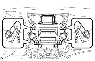
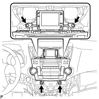
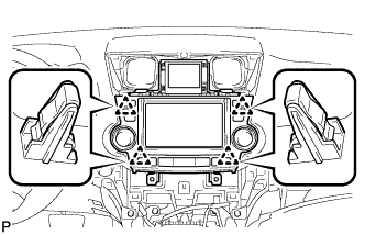
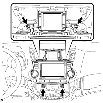
    B173015E01


8. INSTALL INSTRUMENT PANEL SAFETY PAD ASSEMBLY (for Glass Antenna Type)
  1. Engage the 5 claws.

    NOTICE:
    Do not allow the wire harness to get caught in the claws.

  1. Install the 2 bolts <D> and nut <H>.

  1. Install the 2 clips.

    B168377E01

  1. Engage each clamp.

  1. Install the 2 passenger airbag bolts <A>.

    Torque:
    20 N*m{ 204 kgf*cm , 15 ft.*lbf }

  1. Connect each connector and install the instrument panel safety pad assembly.

    B168376E01


9. CONNECT INSTRUMENT PANEL WIRE ASSEMBLY
  1. Check that the ignition switch is off.

  1. Check that the battery negative (-) terminal is disconnected.

    CAUTION:
    Wait for at least 90 seconds after disconnecting the cable to prevent airbag deployment.

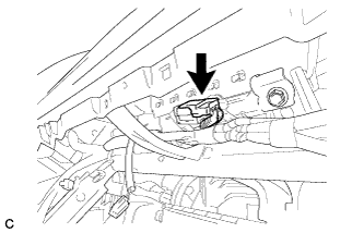
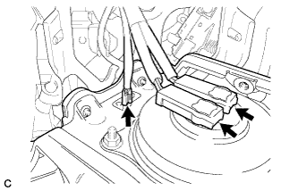
  1. C165103
    Connect the connector.


10. INSTALL FRONT NO. 2 SPEAKER ASSEMBLY (for RH Side)

HINT:
Use the same procedures for the RH side and the LH side.


11. INSTALL NO. 2 INSTRUMENT PANEL SPEAKER PANEL SUB-ASSEMBLY

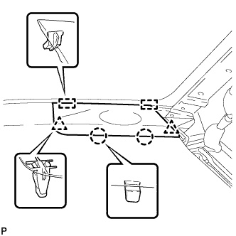
  1. B173014
    Engage the 2 guides.

  1. Engage the 2 claws and 2 clips, and install the No. 2 instrument panel speaker panel sub-assembly.


12. INSTALL FRONT NO. 2 SPEAKER ASSEMBLY (for LH Side)

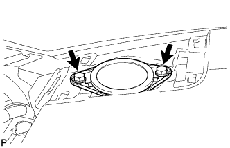
  1. E150560
    Connect the connector.

  1. Install the front No. 2 speaker assembly with the 2 bolts.


13. INSTALL NO. 1 INSTRUMENT PANEL SPEAKER PANEL SUB-ASSEMBLY

  1. B168375
    Engage the 2 guides.

  1. Engage the 2 claws and 2 clips, and install the No. 1 instrument panel speaker panel sub-assembly.


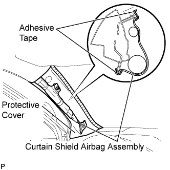
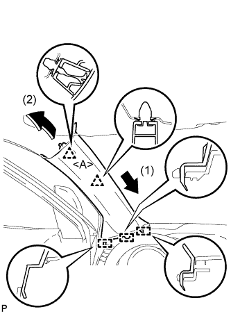
14. INSTALL FRONT PILLAR GARNISH RH

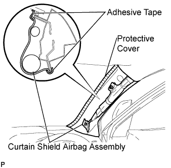
  1. B173685E01
    Remove the protective cover.

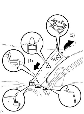
  1. B173683E01
    Install a new clip <A> on the front pillar garnish RH.

  1. Engage the 3 guides and 2 clips, then install the front pillar garnish RH.


15. CONNECT FRONT DOOR OPENING TRIM WEATHERSTRIP RH

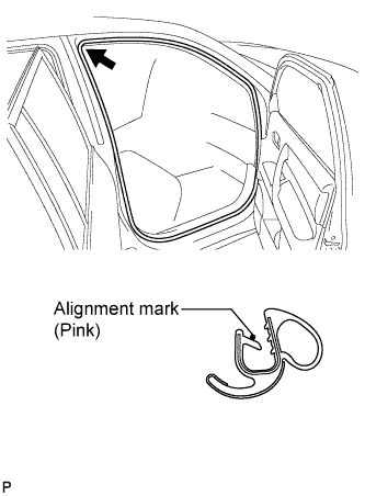
  1. B173239E01
    Align the alignment mark (pink) on the weatherstrip with the protruding portion on the body indicated by the arrow in the illustration, and install the front door opening trim weatherstrip RH.

    NOTICE:
    After installation, check that the corners fit correctly.


16. INSTALL FRONT PILLAR GARNISH LH

  1. B173226E01
    Remove the protective cover.

  1. B173223E01
    Install a new clip <A> on the front pillar garnish LH.

  1. Engage the 3 guides and 2 clips, then install the front pillar garnish LH.


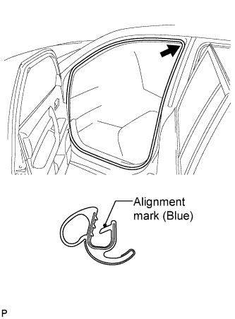
17. CONNECT FRONT DOOR OPENING TRIM WEATHERSTRIP LH

  1. B173235E01
    Align the alignment mark (blue) on the weatherstrip with the protruding portion on the body indicated by the arrow in the illustration, and install the front door opening trim weatherstrip LH.

    NOTICE:
    After installation, check that the corners fit correctly.


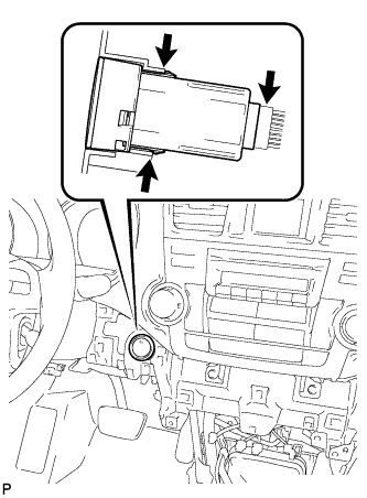
18. INSTALL ENGINE SWITCH (w/ Smart Entry and Start System)

  1. A170658
    Engage the 2 claws to install the switch.

  1. Connect the switch connector.


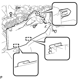
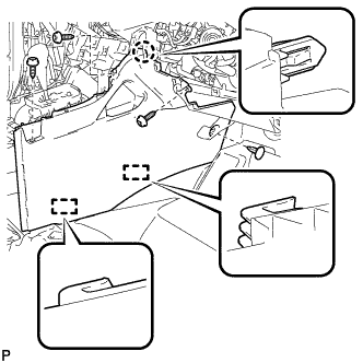
19. INSTALL FRONT NO. 2 CONSOLE BOX INSERT (for LHD)

  1. B168374
    Engage the claw and 2 guides.

  1. Install the front No. 2 console box insert with the 3 screws <F> and clip.


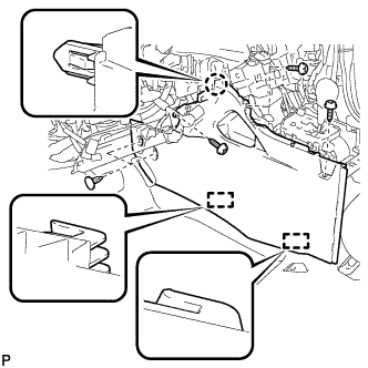
20. INSTALL FRONT NO. 2 CONSOLE BOX INSERT (for RHD)

  1. B173038
    Engage the claw and 2 guides.

  1. Install the front No. 2 console box insert with the 3 screws <F> and clip.


21. INSTALL FRONT NO. 1 CONSOLE BOX INSERT (for LHD)

  1. B168373
    Engage the claw and 2 guides.

  1. Install the front No. 1 console box insert with the 3 screws <F> and 2 clips.


22. INSTALL FRONT NO. 1 CONSOLE BOX INSERT (for RHD)

  1. B173037
    Engage the claw and 2 guides.

  1. Install the front No. 1 console box insert with the 3 screws <F> and clip.


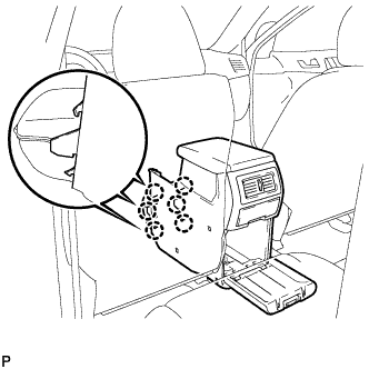
23. INSTALL CONSOLE BOX ASSEMBLY (w/o Rear Air Conditioning System)

  1. B173629
    Engage the 6 claws.

  1. B173628
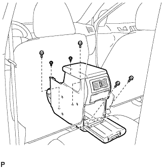
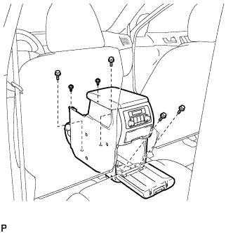
    Install the console box assembly with the 4 bolts and 2 screws.


24. INSTALL CONSOLE BOX ASSEMBLY (w/ Rear Air Conditioning System)

  1. B175149
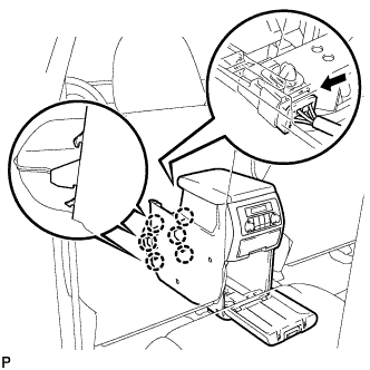
    Engage the 6 claws.

  1. Connect the connector.

  1. B181135
    Install the console box assembly with the 4 bolts and 2 screws.


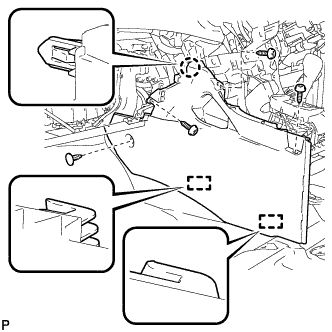
25. INSTALL LOWER REAR CONSOLE BOX
  1. Install the lower rear console box.


26. INSTALL NO. 2 CONSOLE BOX DUCT (w/o Rear Air Conditioning System)

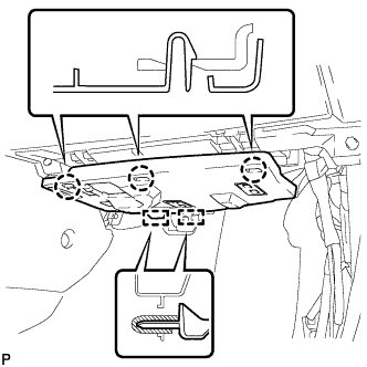
  1. B173013
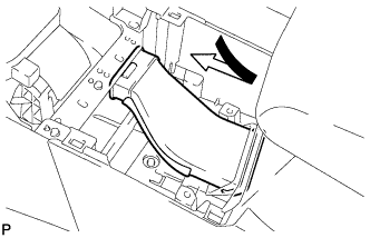
    Install the No. 2 console box duct as shown in the illustration.


27. INSTALL UPPER CONSOLE PANEL SUB-ASSEMBLY

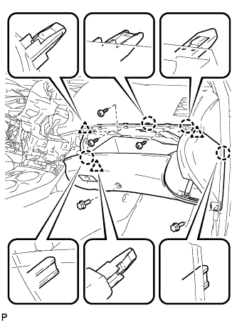
  1. B168372
    Connect the connector.

  1. Engage the 4 claws and 4 clips, and install the upper console panel sub-assembly.


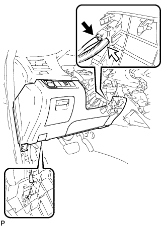
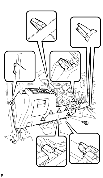
28. INSTALL LOWER INSTRUMENT PANEL SUB-ASSEMBLY
  1. Connect each connector and clamp.

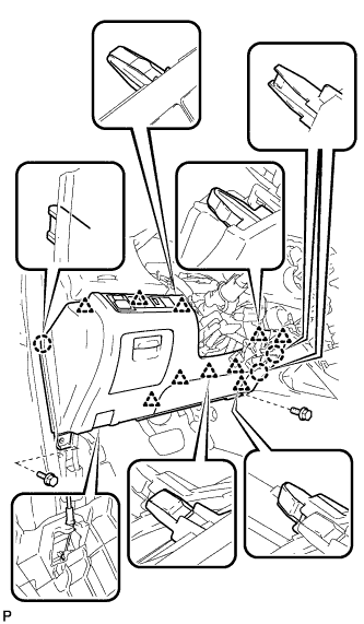
  1. B168370
    Engage the 4 claws and 3 clips.

  1. Install the lower instrument panel sub-assembly with the 2 bolts <B> and 3 screws <F>.


29. INSTALL NO. 2 INSTRUMENT PANEL UNDER COVER SUB-ASSEMBLY

  1. B173000
    Engage the 2 guides.

  1. Engage the 3 claws and install the No. 2 instrument panel under cover sub-assembly.


30. INSTALL COWL SIDE TRIM SUB-ASSEMBLY RH

HINT:
Use the same procedure for the RH side and the LH side.


31. INSTALL FRONT DOOR SCUFF PLATE RH

HINT:
Use the same procedure for the RH side and the LH side.


32. INSTALL LOWER INSTRUMENT PANEL FINISH PANEL SUB-ASSEMBLY (for Manual Air Conditioning System)

  1. B168371
    Connect the hood lock control cable assembly.

  1. Connect each connector.

  1. Engage the 3 claws and 10 clips.

  1. Install the lower instrument panel finish panel sub-assembly with the 2 bolts <B>.


33. INSTALL LOWER INSTRUMENT PANEL FINISH PANEL SUB-ASSEMBLY (for Automatic Air Conditioning System)

  1. B173009
    Connect the hood lock control cable assembly.

  1. Connect each connector and the aspirator duct.

  1. B173021
    Engage the 3 claws and 10 clips.

  1. Install the lower instrument panel finish panel sub-assembly with the 2 bolts <B>.


34. INSTALL COWL SIDE TRIM SUB-ASSEMBLY LH

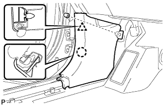
  1. B173227
    Engage the claw and clip, install the cowl side trim sub-assembly LH.

  1. Install the clip.


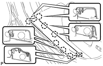
35. INSTALL FRONT DOOR SCUFF PLATE LH

  1. B173224
    Engage the guide and the 8 claws, and install the front door scuff plate LH.


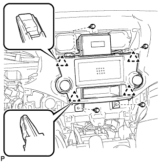
36. INSTALL RADIO RECEIVER ASSEMBLY WITH BRACKET (w/o Navigation System)
  1. Connect each connector.

  1. E150552
    Engage the 4 clips.

  1. E150551
    Install the radio receiver assembly with bracket with the 4 bolts.


37. INSTALL NAVIGATION RECEIVER ASSEMBLY WITH BRACKET (w/ Navigation System)
  1. Connect each connector.

  1. E150545
    Engage the 4 clips.

  1. E150544
    Install the navigation receiver assembly with bracket with the 4 bolts.


38. INSTALL INTEGRATION CONTROL AND PANEL ASSEMBLY WITH BRACKET (w/o Radio Receiver)
  1. Connect each connector.

  1. B173010
    Engage the 4 clips.

  1. Install the integration control and panel assembly with bracket with the 4 bolts <D>.


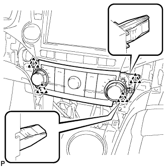
39. INSTALL HEATER CONTROL AND ACCESSORY ASSEMBLY (for Manual Air Conditioning System)
  1. Connect the connector.

  1. E150368
    Engage the 4 clips and install the heater control and accessory assembly.


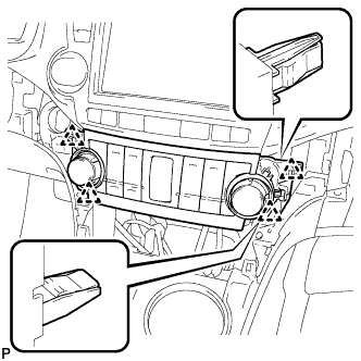
40. INSTALL AIR CONDITIONING CONTROL ASSEMBLY (for Automatic Air Conditioning System)
  1. Connect the connector.

  1. E150367
    Engage the 4 clips and install the air conditioning control assembly.


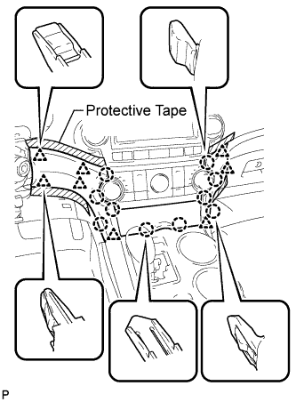
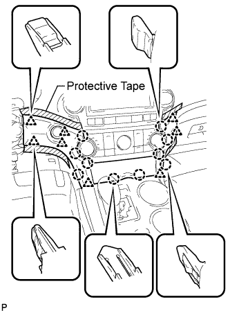
41. INSTALL CENTER INSTRUMENT CLUSTER FINISH PANEL ASSEMBLY (w/o Smart Entry and Start System)

  1. B184679E01
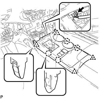
    Apply protective tape to the areas shown in the illustration.

  1. Connect each connector.

  1. Engage the 10 claws and 8 clips, and install the center instrument cluster finish panel assembly.

    NOTICE:
    Do not the damage the instrument panel safety pad assembly and lower instrument panel finish panel sub-assembly.


42. INSTALL CENTER INSTRUMENT CLUSTER FINISH PANEL ASSEMBLY (w/ Smart Entry and Start System)

  1. B184681E01
    Apply protective tape to the areas shown in the illustration.

  1. Connect each connector.

  1. Engage the 10 claws and 8 clips, and install the center instrument cluster finish panel assembly.

    NOTICE:
    Do not the damage the instrument panel safety pad assembly and lower instrument panel finish panel sub-assembly.


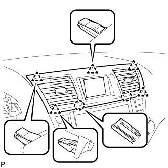
43. INSTALL CENTER INSTRUMENT PANEL REGISTER ASSEMBLY

  1. B168369
    Engage the 2 claws and 5 clips, and install the center instrument panel register assembly.


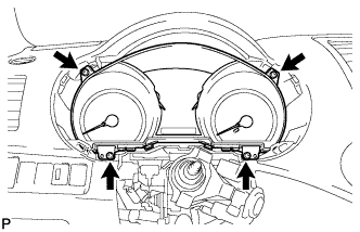
44. INSTALL COMBINATION METER ASSEMBLY
  1. Connect the connector.

  1. B168365
    Install the combination meter assembly with the 4 screws <F>.


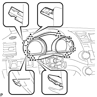
45. INSTALL INSTRUMENT CLUSTER FINISH PANEL ASSEMBLY

  1. B168364
    Engage the 4 claws and 4 clips, and install the instrument cluster finish panel assembly.


46. POSITION FRONT WHEELS STRAIGHT AHEAD

47. INSTALL TURN SIGNAL SWITCH ASSEMBLY WITH SPIRAL CABLE SUB-ASSEMBLY

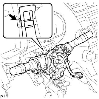
  1. C166129
    Using pliers, engage the claw. Install the turn signal switch assembly with spiral cable sub-assembly to the steering column assembly.

  1. Connect the connectors to the turn signal switch assembly with spiral cable sub-assembly.


48. INSTALL STEERING COLUMN COVER

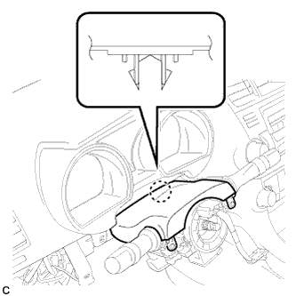
  1. C165716
    Engage the claw to install the upper steering column cover.

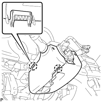
  1. C166128
    Engage the 2 claws to install the lower steering column cover.

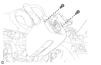
  1. C165715
    Install the 2 screws.

    Torque:
    2.0 N*m{ 20 kgf*cm , 18 in.*lbf }


49. ADJUST SPIRAL CABLE SUB-ASSEMBLY
  1. Check that the ignition switch is off.

  1. Check that the battery negative (-) cable is disconnected.

    CAUTION:
    Wait for at least 90 seconds after disconnecting the cable to prevent airbag deployment.

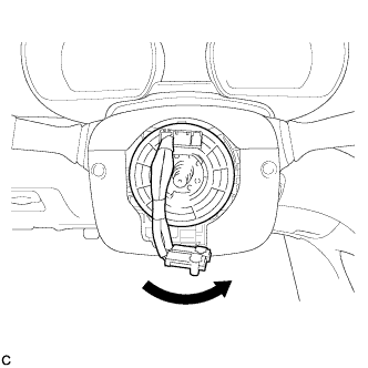
  1. C165096
    Rotate the spiral cable counterclockwise slowly by hand until it stops.

    NOTICE:
    Do not turn the spiral cable using the airbag wire harness.

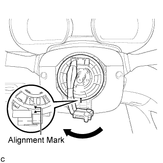
  1. C165097E01
    Rotate the spiral cable clockwise approximately 2.5 turns to align the marks.

    NOTICE:
    Do not turn the spiral cable using the airbag wire harness.

    HINT:
    The spiral cable will rotate approximately 2.5 turns to both the left and right from the center.


50. INSTALL STEERING WHEEL ASSEMBLY

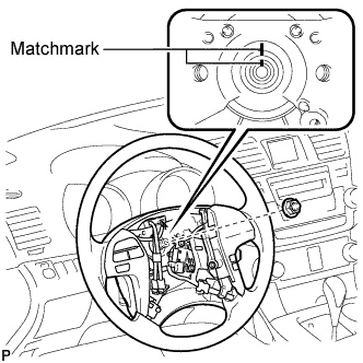
  1. C165708E01
    Align the matchmarks on the steering wheel assembly and steering main shaft.

  1. Install the steering wheel assembly set nut.

    Torque:
    50 N*m{ 510 kgf*cm , 37 ft.*lbf }

  1. Connect the connectors to the spiral cable sub-assembly.


51. INSPECT STEERING WHEEL CENTER POINT

52. INSTALL STEERING PAD
  1. Check that the ignition switch is off.

  1. Check that the battery negative (-) terminal is disconnected.

    CAUTION:
    Wait for at least 90 seconds after disconnecting the cable to prevent airbag deployment.

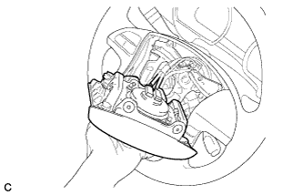
  1. C165092
    Support the steering pad with one hand as shown in the illustration.

  1. C165093
    Connect the 2 airbag connectors to the steering pad.

    NOTICE:
    When handling the airbag connector, take care not to damage the airbag wire harness.

  1. Connect the horn connector to the steering pad.

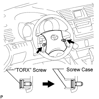
  1. Confirm that the circumference groove of the "TORX" screw fits in the screw case, and place the steering pad onto the steering wheel assembly.

  1. C166982E01
    Using a "TORX" socket wrench (T30), tighten the 2 "TORX" screws.

    Torque:
    8.8 N*m{ 90 kgf*cm , 78 in.*lbf }


53. INSTALL LOWER NO. 2 STEERING WHEEL COVER

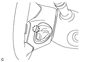
  1. C165091
    Install the lower No. 2 steering wheel cover with the claw.


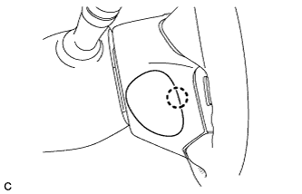
54. INSTALL LOWER NO. 3 STEERING WHEEL COVER

  1. C165090
    Install the lower No. 3 steering wheel cover with the claw.


55. CONNECT CABLE TO NEGATIVE BATTERY TERMINAL

NOTICE:
When disconnecting the cable, some systems need to be initialized after the cable is reconnected (Click here).


56. INSPECT STEERING PAD

  1. C166979
    With the steering pad installed on the vehicle, perform a visual check. If there are any defects as mentioned below, replace the steering pad with a new one:
    1. Cuts, minute cracks or marked discoloration on the steering pad top surface or grooves.

  1. Make sure that the horn sounds.

    HINT:
    If the horn does not sound, inspect the horn system (Click here).


57. INSPECT SRS WARNING LIGHT
  1. Inspect the SRS warning light (Click here).
← INSTALLATION (May 2007 – Jul 2008)INSTALLATION (from Jul 2010) →